High-performance drive circuitry for capacitive transducers

Active Publication Date: 2005-11-01
BONIN WAYNE
View PDF2 Cites 31 Cited by
  • Summary
  • Abstract
  • Description
  • Claims
  • Application Information

AI Technical Summary

Benefits of technology

[0012]An object of the invention was to create a circuit that would have the lowest possible noise, so that the transducer resolution would be at least 1 part in 1,000,000. Other objects of the invention were to minimize the physical size, cost, and power dissipation of the circuit.
[0013]Noise was minimized by several means. One means is by using a very low noise voltage reference integrated circuit (IC) with special filtering to limit the reference noise to about 3 μVpp. Other means include operating the buffer amplifier at a gain of 10 to minimize the effect of noise in components in the signal path after the buffer amplifier, using an analog switch to synchronously demodulate the pickup electrode signal rather than an analog multiplier which adds noise, using a differential amplifier with a high common mode rejection ratio (CMRR) to reject electrical interference noise picked up by the transducer from other equipment, and choosing components and circuit confi

Problems solved by technology

In practice there are many factors that tend to introduce errors to the output voltage, such as temperature sensitivities in gain and offset voltage, non-linearity, and noise.
This circuitry is simple and inexpensive, and performs quite well for low to medium performance applications, but has significant limitations for high performance applications requiring linearity accuracy of better than 1%, or resolution of better than 1 part in 100,000 of the full scale output.
Unfortunately the means' of implementing this disclosed by Thomas are rather complicated and expensive, using up/down counters in combination with digital to analog converters in some cases, and transformers in other cases.
This adds a delay to one channel, so that when they are re-com

Method used


Image

  • High-performance drive circuitry for capacitive transducers
  • High-performance drive circuitry for capacitive transducers
  • High-performance drive circuitry for capacitive transducers

Examples


Embodiment Construction

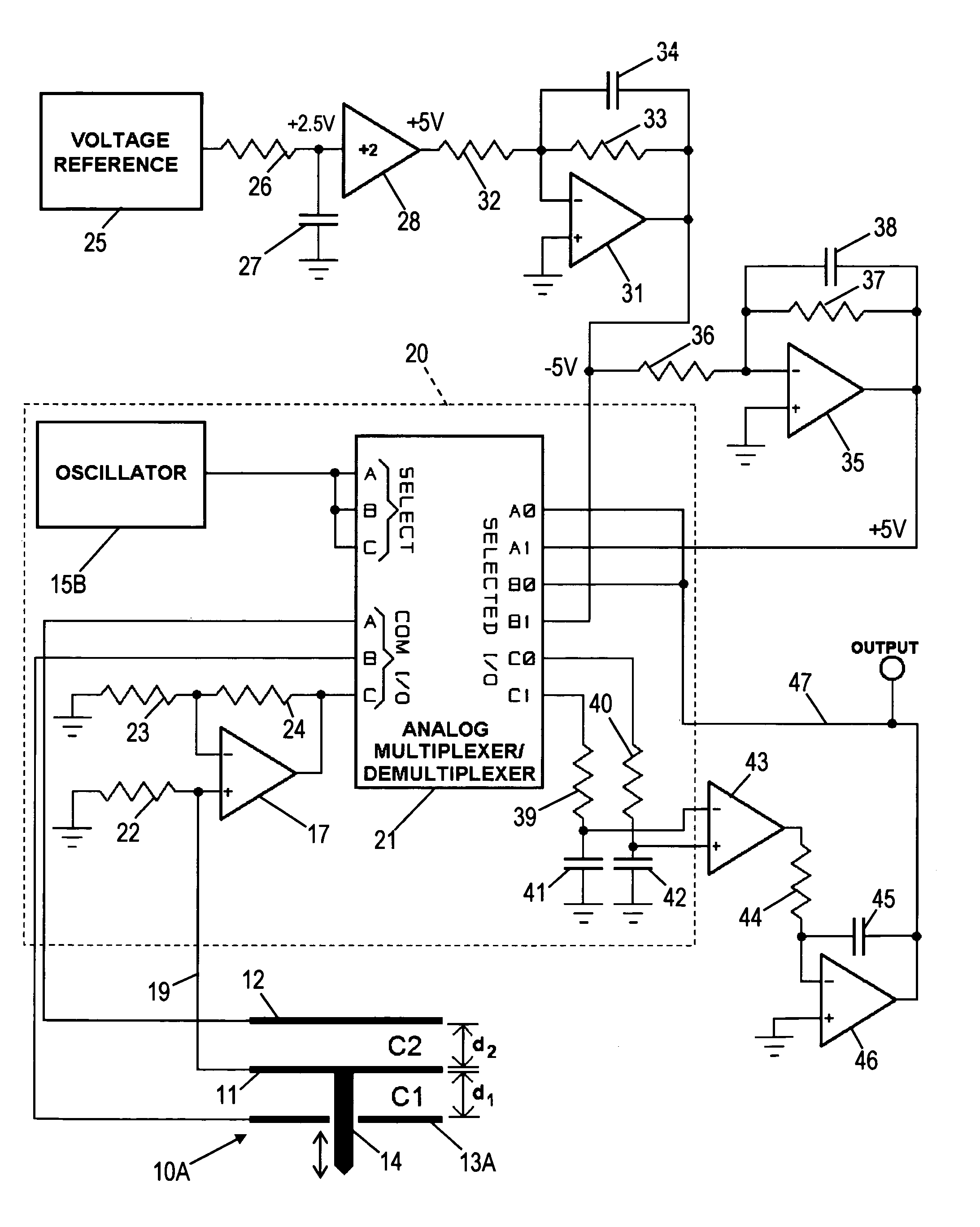
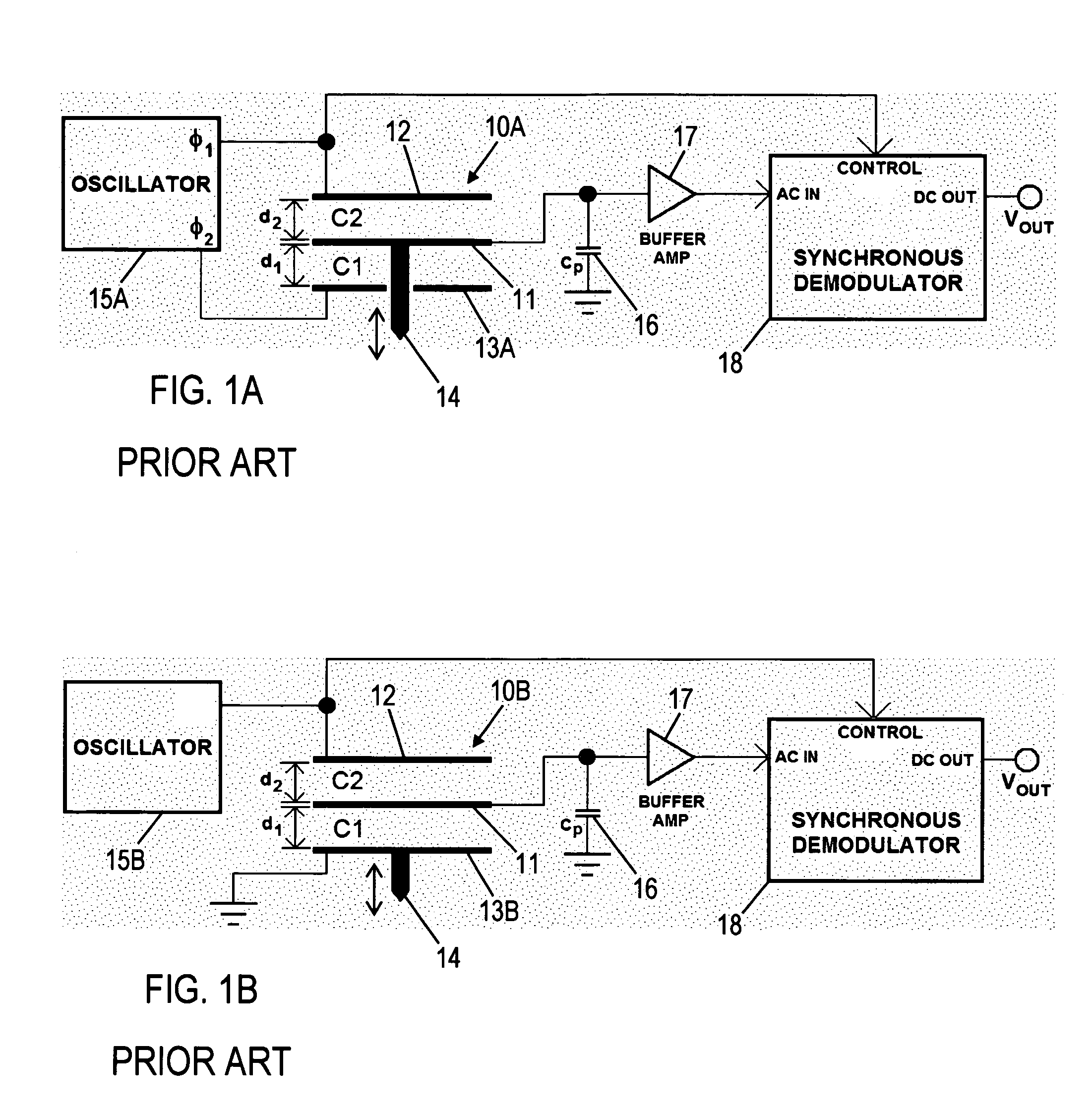
[0026]Before considering the circuit of this invention, an understanding of the prior art circuits, and the transducers used with them is helpful. The circuitry presented here operates with two variations of three electrode capacitive transducers. Transducer 10A shown in FIG. 1A has a first drive electrode 12, a second drive electrode 13A, and a pickup electrode 11. Pickup electrode 11 is located between drive electrodes 12, 13A and is movable with respect to the two drive electrodes. Drive electrode 13A is shown with a hole to permit passage through it by probe tip 14. Probe tip 14 interacts with a surface or sample being tested (not shown), and transmits force or displacement between the sample and pickup electrode 11. It is also possible to extend pickup electrode 11 out the side past the drive electrodes, in which case a hole is not required. In the case of an accelerometer, force is applied to pickup electrode 11 directly by the acceleration and neither the hole nor the extensi...


PUM


Abstract

Drive circuitry for capacitive displacement transducers includes an oscillator, a precision low noise voltage reference with added noise reduction circuitry, a synchronous demodulator consisting of a single pole double throw analog switch, one or more transducer electrode drive signals generated by one or more additional analog switches, and feedback circuitry to modify the amplitude of the electrode drive signal based on the circuit output signal, to improve the accuracy of the output signal.

Description

CROSS-REFERENCE TO RELATED APPLICATIONS[0001]This application claims the benefit of PPA Ser. No. 60 / 470,664, filed May 15, 2003 by the present inventor.STATEMENT REGARDING FEDERALLY SPONSORED RESEARCH OR DEVELOPMENT[0002]Not ApplicableREFERENCE TO SEQUENCE LISTING, A TABLE, OR A COMPUTER PROGRAM LISTING COMPACT DISK APPENDIX[0003]Not ApplicableBACKGROUND OF THE INVENTION[0004]This invention relates to electronic circuitry used to operate capacitive transducers, for example for use in displacement and force-responsive devices.[0005]Capacitive transducers use various configurations of capacitor electrodes along with springs, diaphragms or other support mechanisms to sense acceleration, force, weight, pressure, displacement or position. Capacitive transducers have much higher output signal than strain gauge transducers, giving them a potential advantage in signal to noise ratio (SNR) and reduced susceptibility to drift, but capacitive transducers also generally have a much higher imped...

Claims


Application Information

Patent Timeline
IPC IPC(8): H03B1/00G01D5/241
CPCG01D5/2417
Inventor BONIN, WAYNE
Owner BONIN WAYNE
Why Eureka
Try Eureka