
Method for simulating an ocular optical system and apparatus therefor

a technology of optical system and optical system, applied in the field of simulating optical system, can solve the problems of image distortion different from that in the actual perceived image, insufficient simulating visual perception with a single eye,

Active Publication Date: 2006-05-02
HOYA CORP
View PDF8 Cites 11 Cited by
  • Summary
  • Abstract
  • Description
  • Claims
  • Application Information

AI Technical Summary

Problems solved by technology

Since a person observes things with both eyes, the simulation of visual perception with a single eye is not always sufficient for the purpose of expressing and evaluating the visual perception of external thing observed through spectacle glasses.
However, in a monocular rotation-based retinal image, the asymmetry in the horizontal direction is faithfully reproduced and the image has distortion different from that in the actually perceived image.

Method used


Image

  • Method for simulating an ocular optical system and apparatus therefor
  • Method for simulating an ocular optical system and apparatus therefor
  • Method for simulating an ocular optical system and apparatus therefor

Examples


embodiment 1

(A) Embodiment 1

[0044]The method for simulating an ocular optical system of Embodiment 1 of the present invention will be described as follows with reference to the above-described Figures.

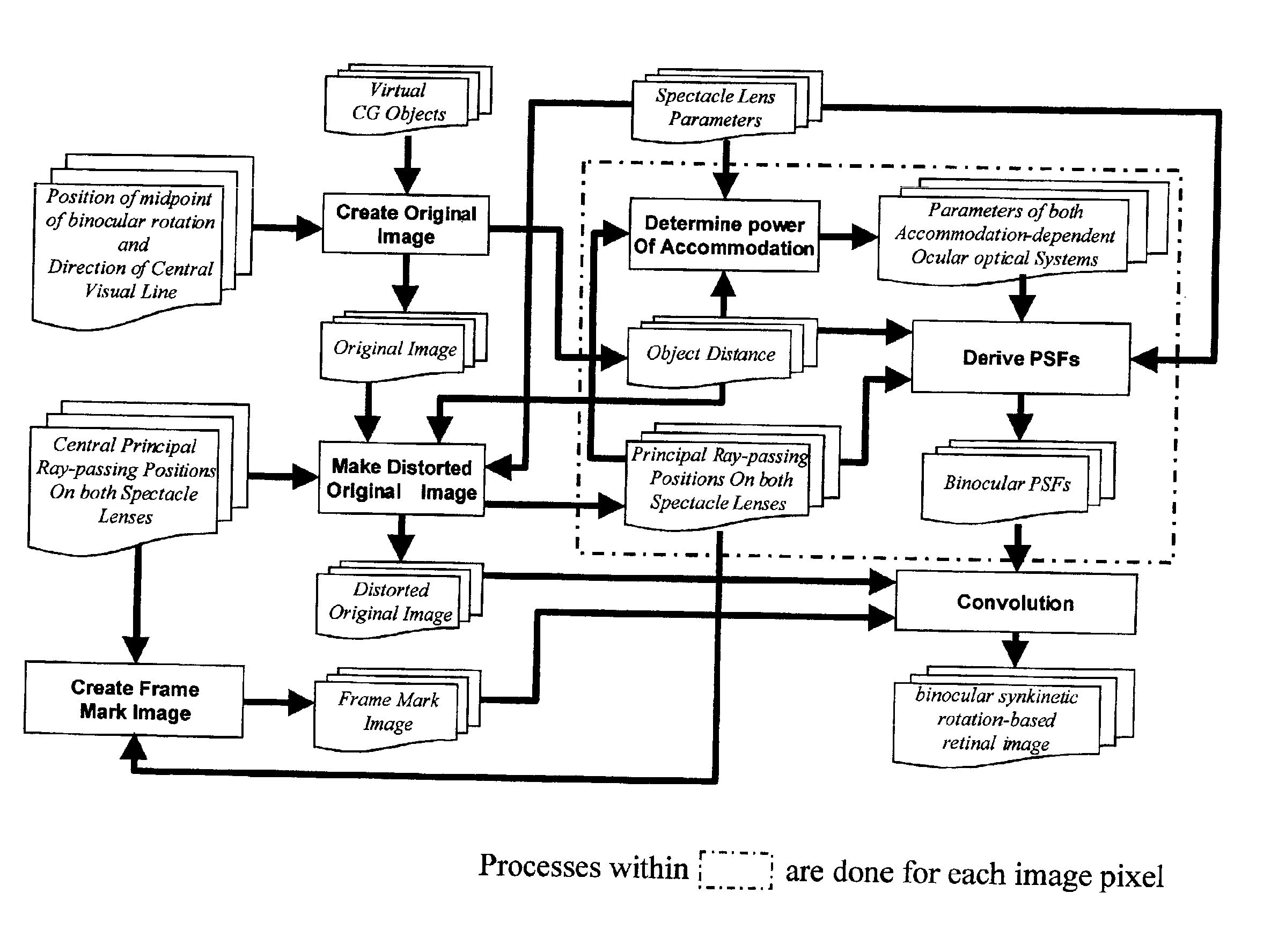
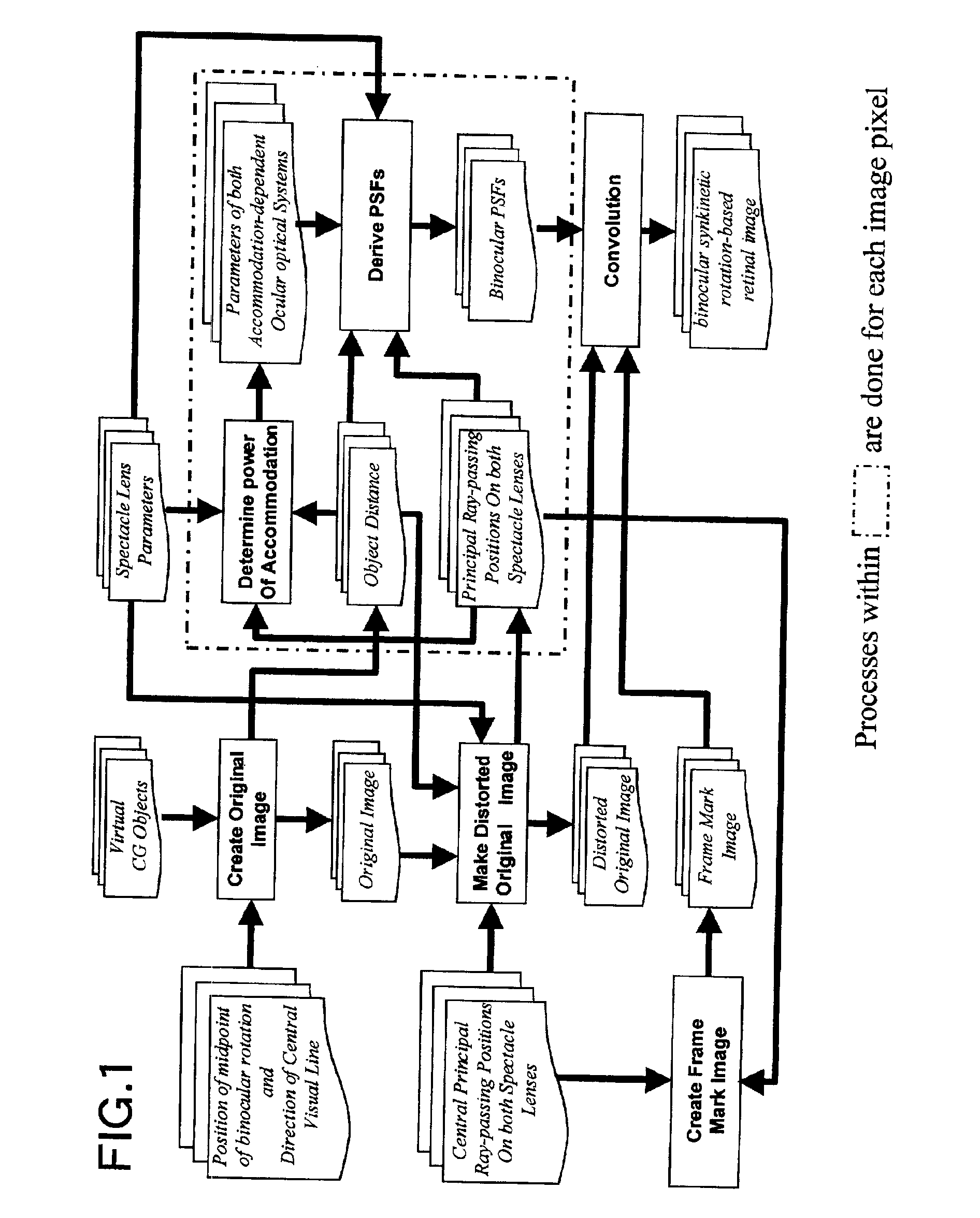
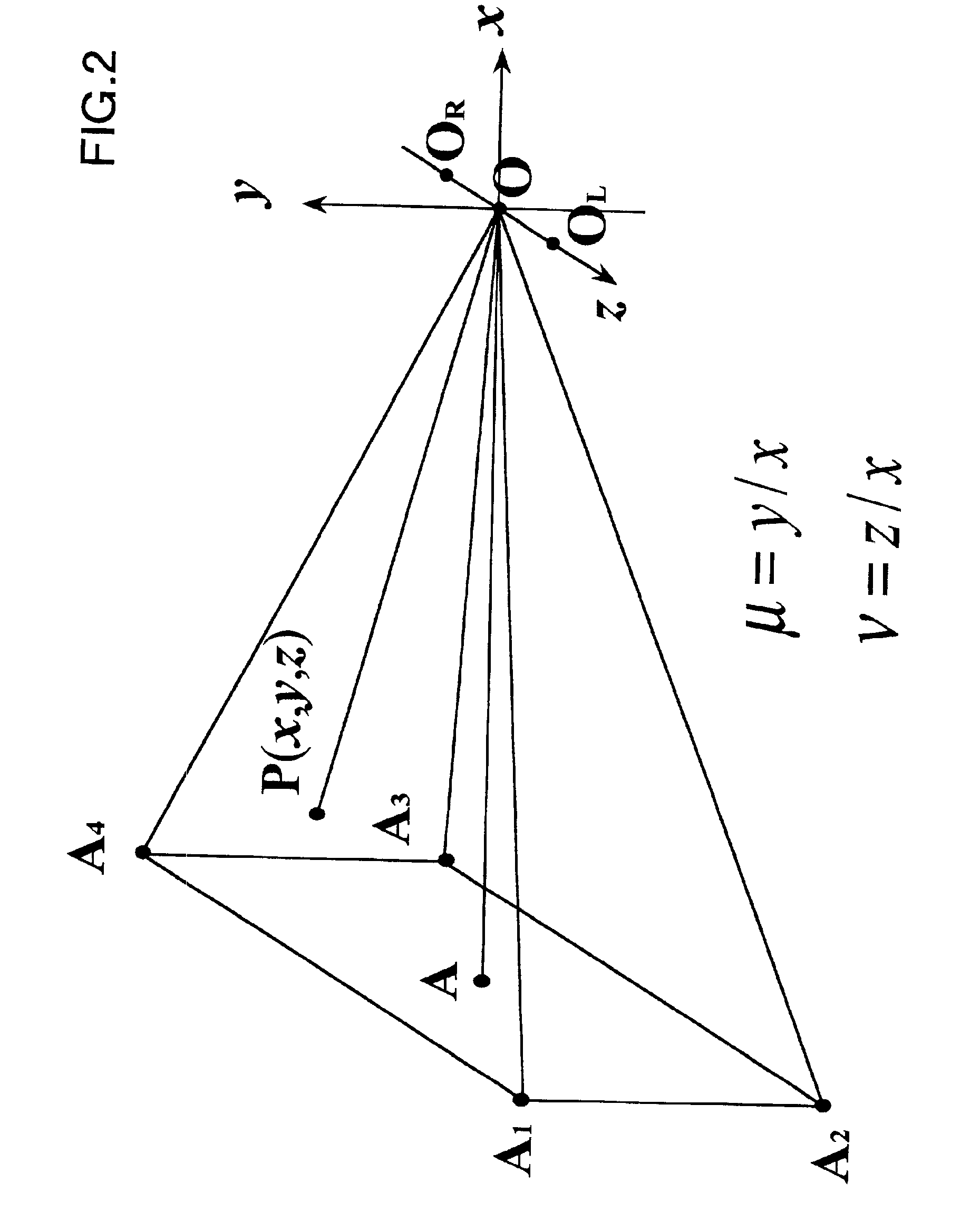
[0045]The method for simulating an ocular optical system of the present embodiment is a method for creating a still image of a binocular synkinetic rotation-based retinal image when three-dimensional virtual objects created by computer graphics are observed through a pair of spectacle lenses placed in front of the right and left eyes, respectively. The binocular synkinetic rotation-based retinal image is an image which is created, based on specific assumptions found by the present inventor, by treating the above image of three-dimensional virtual objects with optical effects taken into consideration using image processing technology in order to approximately reproduce the image as perceived by the eyes. In other words, the binocular synkinetic rotation-based retinal image is not an optical image p...

embodiment 2

B. Embodiment 2

[0097]In the second embodiment, many still binocular synkinetic rotation-based retinal images such as those produced in Embodiment 1 are created at a plurality of points in time, while the position of the midpoint of binocular rotation, the direction of the central visual line, both principal ray-passing positions on spectacle lenses, the amount of deformation and displacement of the virtual objects are changed. Therefore, the method of the present embodiment is essentially similar to the method of Embodiment 1 except that the method further comprises: (1) creating a story of changes with time of the position of the midpoint of binocular rotation, the direction of the central visual line, both principal ray-passing positions on spectacle lenses, the amount of deformation and displacement of the virtual objects and (2) creating a video image by editing the still images at a plurality of points in time. FIG. 12 shows a diagram exhibiting the overall flow of the method. ...


PUM


Abstract

A method and apparatus for simulating an ocular optical system that enables simulating visual perception having fluctuation, distortion and blur in the use of spectacle lenses such as progressive addition lenses. A binocular synkinetic rotation-based retinal image is created, defined as an image obtained by rotating both eyeballs toward each object point in a visual field, then, uniting images projected on the foveae of right and left eyes and to produce a united image. An original image is created wherein the midpoint of binocular rotation is placed at a specific position, and objects within a specific pyramidal visual field are observed. A distorted original image is obtained by observing the visual field through spectacle lenses using the ray tracing method. Point Spread Functions (PSF's) are derived, wherein right and left monocular PSF's are obtained and a united binocular PSF is derived from both monocular PSF's. Visual perception through spectacle lenses is simulated by convoluting of the distorted original image and the united binocular PSFs with respect to each pixel of the original image.

Description

FIELD OF THE INVENTION[0001]The present invention relates to a method for simulating an ocular optical system in accordance with which a scene of external things actually seen by an observer through two spectacle lenses each placed in front of right and left eyes is simulated, and to an apparatus therefor.BACKGROUND OF THE INVENTION[0002]A method for simulating an ocular optical system in accordance with which a scene of external things actually seen by an observer through spectacle lenses placed in front of each of right and left eyes is simulated and an apparatus therefor have been disclosed by the present inventor in Japanese Patent Application No. Heisei 10(1998)-288077.[0003]In the method and the apparatus described above, a scene of external things actually seen by an observer through a lens placed in front of a single eye is simulated. In accordance with the above method and by using the above apparatus, the actual human perception can be taken into consideration and the visu...

Claims


Application Information

Patent Timeline
Patent Type & Authority Patents(United States)
IPC IPC(8): G06F17/10A61B3/00G06F7/48G02C7/02
CPCG02C7/028G02C7/02
Inventor QI, HUA
Owner HOYA CORP
Learn More