Anti-bird roosting device

a technology of anti-birds and roosters, which is applied in the field of anti-bird roosting devices, can solve the problems of unbalanced rings, less effective configuration, and high production cost of devices

Inactive Publication Date: 2006-05-09
FINKELSTEIN JOSEPH
View PDF23 Cites 33 Cited by
  • Summary
  • Abstract
  • Description
  • Claims
  • Application Information

AI Technical Summary

Benefits of technology

[0024]Accordingly, it is a principal object of the present invention to overcome the above mentioned disadvantages and provide a superior device for preventing birds from landing and perching or roosting on exposed surfaces.

Problems solved by technology

The dimensions of the rings are such that when birds tried to perch they unbalanced the rings.
This configuration is thought to be less effective because over a period of time, bird feces fills in the gaps between the spikes and then the birds can freely perch.
This device seems to be costly in terms of production cost.
This device appears somewhat hazardous to install, as the repellant arms seem to be quite jagged.
In addition, the continuous, filled, base strip seems inconvenient to secure to the surface, to be protected.
In this device, the protection afforded the surface is limited, as the spikes are almost vertical.
The device appears to be rigid in construction, which may hinder installation and hamper adaptation to the changing needs of the user.
These tend to make the surface of the windowsill, etc., sticky.
Consequently, dust and other filth adhere to the said surface in a short period of time, rendering the chemical preparation useless.
In some instances, such as the devices based on magnetic field and optical determent, the effectivity of the devices has not been firmly established.
Devices using cables and the like, mounted above the surface of interest, demand a system of supports, which complicate the solution.
The approach using a base element coupled with vertically oriented projections would seem less efficient, as bird feces will eventually fill in the gaps between the projections.
Continuous, filled, base strip elements would seem to be cumbersome in installation and less given to easy dimensional adaptation.

Method used


Image

  • Anti-bird roosting device
  • Anti-bird roosting device
  • Anti-bird roosting device

Examples


Embodiment Construction

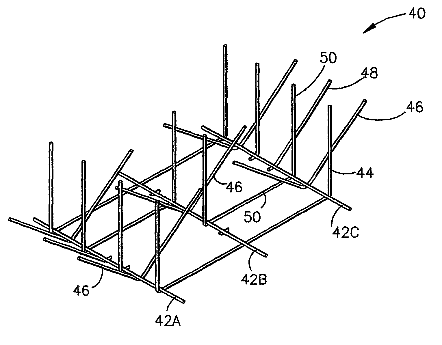
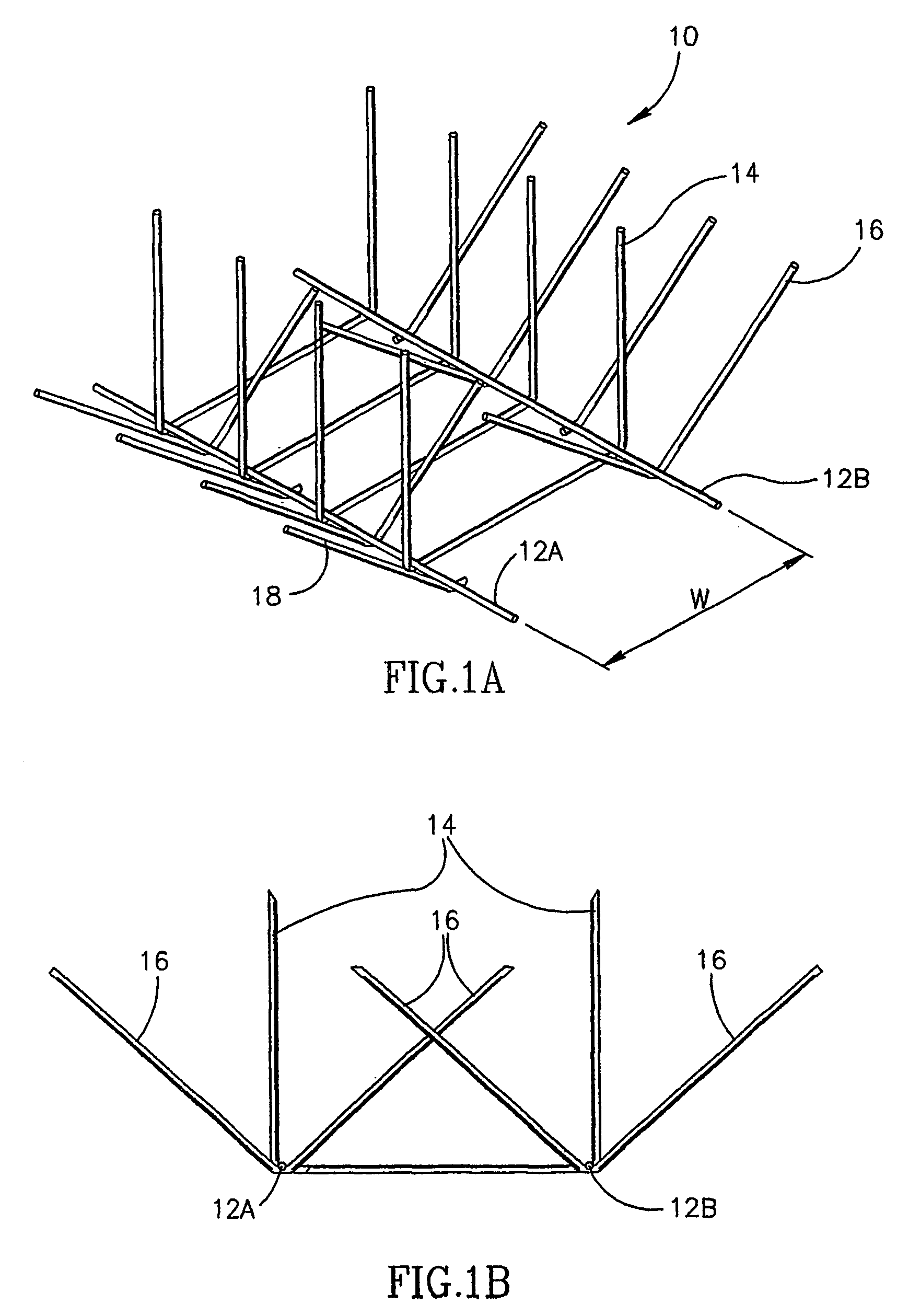
[0052]Referring now to FIG. 1A, there is shown a perspective view of the preferred embodiment of a lightweight, easily mounted and easily configured anti-bird roosting device 10, constructed in accordance with the principles of the present invention. The device 10 comprises a plurality of base-member elements 12a–b, which run parallel, one with the other, and a plurality of top-member spike elements, fabricated as several variant forms, shown in FIGS. 1A–1B. Hereafter, the term “variant” will be used to indicate an alternate form of the spike element, using the same reference number.

[0053]In FIG. 1A, top-member spike element variants 14 connect the base-member elements, one to another. The spikes of this top-element variant project vertically, in this embodiment. Spike element variants 16 and 18 are each bent into an angular form. In variant 16, both arms are equal in length, one arm projects inwardly and one arm projects outwardly. In variant 18, one arm is very short, essentially ...


PUM


Abstract

An anti-bird roosting device for protecting an area, comprising at least a pair of cooperating base elements mounted on the area to be protected, and a plurality of projecting spikes, supported on the base elements and projecting away therefrom into a space above the area to be protected. The spikes are provided in a pattern of interspersed combinations of vertical, obtuse and acute angle-forming projections, in a high spike density that prevents roosting in the protected space. Thus, each point in the area to be protected is defended by more than one spike, each spike coming from a different direction, so as to cross-defend each other, creating a perimeter envelope defense of the air volume surrounding the base elements. Each device is easily and inexpensively prepared as a continuous mesh, whose dimensions can be constructed in standard sizes or in accordance with the needs of the user. The element diameter is typically approximately two millimeters. The small element diameter makes the entire device hard to see from a distance so that it does not detract from the building's aesthetics.

Description

FIELD OF THE INVENTION[0001]The present invention relates to a new device for preventing birds from landing or perching on exposed surfaces and more specifically to a device comprised of two or more base-member elements, connected to each other, via a plurality of top-members, each top-member having spike end-segments, which are easily configured, so as to supply the user with maximum anti-bird roosting protection.BACKGROUND OF THE INVENTION[0002]The prior art of anti-bird perching or roosting devices was based on one of several approaches to deter birds from landing. These approaches were either used alone, or in combination one with the other. The approaches may be divided into a number of categories:[0003]Magnetic[0004]Optical[0005]Sloped Surface[0006]Mechanical: Cables[0007]Unstable perch[0008]Projections[0009]Chemical[0010]Several inventors based their devices on the principle of creating a variable magnetic field. This is based on the theory that a magnetic field tends to repe...

Claims


Application Information

Patent Timeline
Patent Type & Authority Patents(United States)
IPC IPC(8): A01M29/00A01M29/32
CPCA01M29/32
Inventor FINKELSTEIN, JOSEPH
Owner FINKELSTEIN JOSEPH
Why Eureka
Try Eureka