
Spraying head

a head and head technology, applied in the field of head, can solve the problems of clogging of the nozzle, subjected to very demanding conditions, etc., and achieve the effects of effective humidification of the intake air, faster and more effective transition to the retracted position, and advantageous and efficient solution

Inactive Publication Date: 2006-05-09
MARIOFF CORP OY
View PDF11 Cites 3 Cited by
  • Summary
  • Abstract
  • Description
  • Claims
  • Application Information

AI Technical Summary

Benefits of technology

The present invention relates to a spraying head for humidifying the intake air of piston engines. The spraying head is designed to be movable between at least two positions, a first position in which it is retracted and a second position in which it is protruding. The spraying head is introduced into the air intake duct of the engine and is subjected to very demanding conditions, such as high temperatures and high flow rates of air. The invention aims to provide a spraying head that can effectively humidify the intake air without causing any obstacles to the air flow when not in use. The spraying head is designed to be in a retracted position when not in use, which prevents it from interfering with the air flow. The nozzles used in the spraying head are designed to be clean and not clogging when not in use. The spraying head is held in place by a spring element that returns it to its retracted position when not in use. The invention provides a solution for reducing noxious emissions in piston engines and achieves efficient humidification of the intake air.

Problems solved by technology

When the spraying head is mounted in its position of application in the air intake duct of the engine, e.g. in connection with a turbocharged diesel engine before and / or after the compressor of the turbocharger, before and / or after a possible intercooler, it is subjected to very demanding conditions.
An additional impediment may be the clogging of the nozzles especially when the nozzle head is not in use.

Method used


Image

  • Spraying head
  • Spraying head
  • Spraying head

Examples


Embodiment Construction

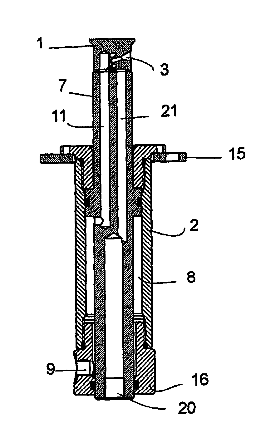
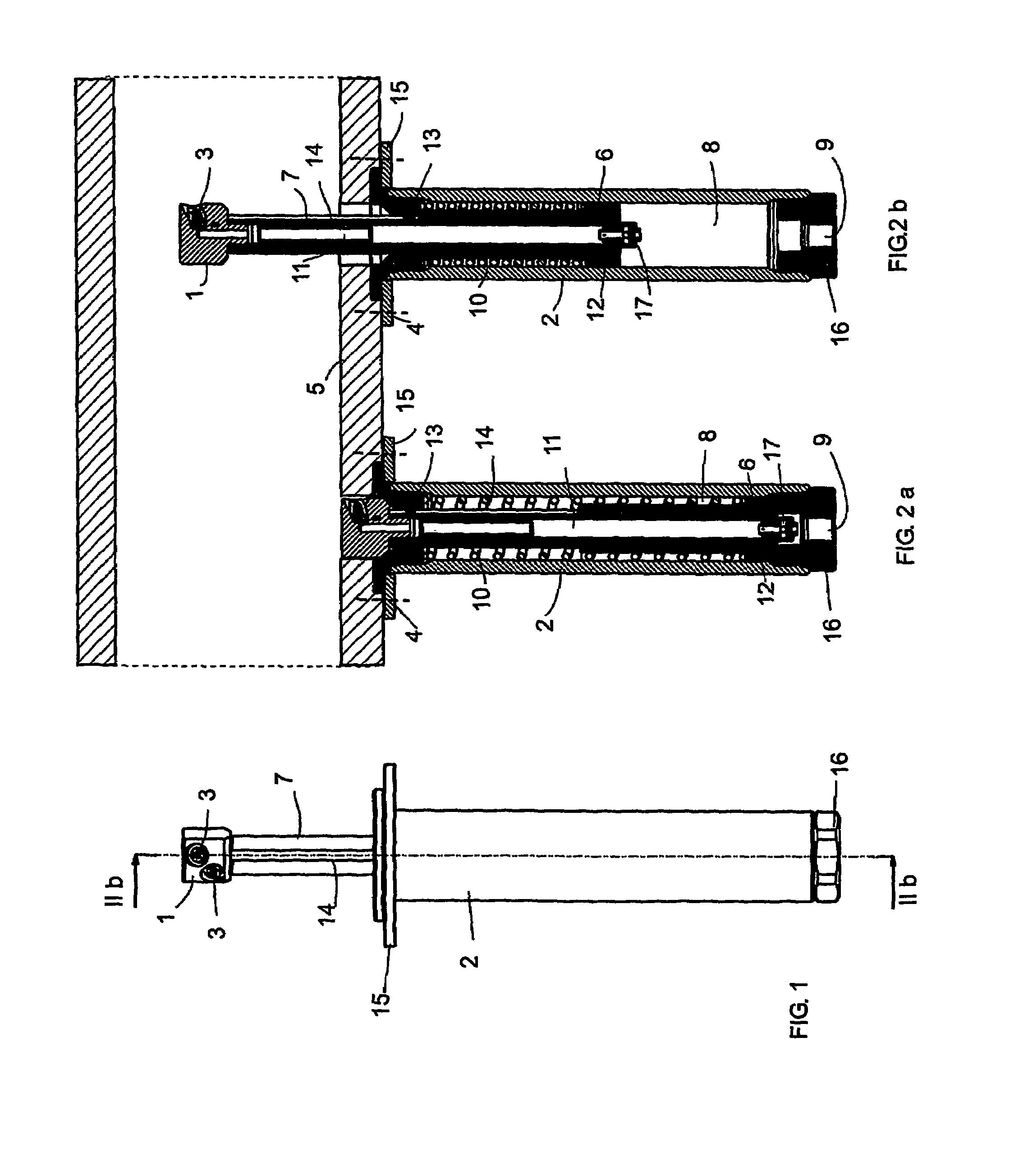
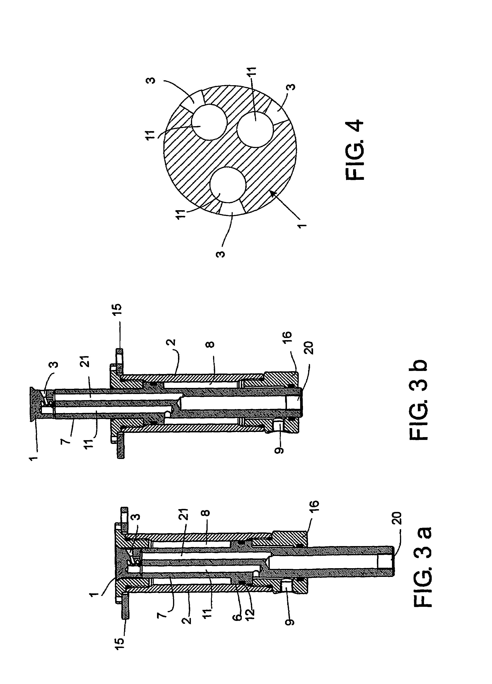
[0016]FIGS. 1, 2a and 2b present an embodiment of the spraying head of the invention. A spraying head for humidifying the intake air of a piston engine, said spraying head 1 comprising at least one nozzle 3 for supplying a liquid humidifying the intake air into the air intake duct 5 or into a space leading to the air intake duct of the engine. The spraying head is movable between at least two positions, a first position, in which first position the spraying head is retracted, and a second position, in which second position the spraying head 1 is protruding. In the non-active state, in the first position (FIG. 2a, 3a), the spraying head is in a retracted position, whereas in the active state, in the second position (FIG. 2b, 3b), at least one nozzle 3 of the spraying head extends to a position inside the air intake duct relative to the level of the edges of the spraying head holder 2 or and / or the interior surface of the air intake duct 5.

[0017]The holder 2 is provided with at least ...


PUM


Abstract

A spraying head for the humidification of the intake air of a piston engine, said spraying head comprising at least one nozzle (3) for supplying a liquid humidifying the intake air into the air intake duct or into a space leading to the air intake duct of the engine. The spraying head (1) is movable between at least two positions, a first position (FIG. 2a), in which first position the spraying head is retracted, and a second position (FIG. 2b), in which second position the spraying head is protruding.

Description

BACKGROUND OF THE INVENTION[0001]The present invention relates to a spraying head as defined in the preamble of claim 1 for humidifying intake air with an aqueous mist.[0002]The exhaust gases of piston engines, in particular diesel engines, contain many kinds of noxious combustion products. At the high combustion temperatures, the combustion process in the cylinder of a piston engine produces nitrogen oxides (NOx), which are emitted together with the exhaust gases into the atmosphere. Because of the negative environmental effects of nitrogen oxide emissions, efforts are undertaken to minimize their production.[0003]As is known, adding water to the combustion process reduces the generation of nitrogen oxides. This phenomenon is based on the cooling effect of water. In practice, the introduction of water into the combustion process in a piston engine is often implemented by injecting water into the intake air. These arrangements are advantageous in respect of the shaft efficiency of t...

Claims


Application Information

Patent Timeline
Patent Type & Authority Patents(United States)
IPC IPC(8): F02B47/02B05B15/70B05B15/74F02B3/06F02M25/028
CPCF02M25/028F02M25/0225B05B15/10F02B3/06Y02T10/121B05B15/74Y02T10/12
Inventor SUNDHOLM, GORAN
Owner MARIOFF CORP OY
Learn More