Hand power tool with a pneumatic striking mechanism

a technology of pneumatic striking mechanism and hand power tool, which is applied in the direction of manufacturing tools, percussive tools, portable drilling machines, etc., can solve the problems of only being able to close the control opening insufficiently and the efficiency of the striking mechanism suffers, so as to increase the efficiency of the striking mechanism

Inactive Publication Date: 2006-05-09
ROBERT BOSCH GMBH
View PDF13 Cites 16 Cited by
  • Summary
  • Abstract
  • Description
  • Claims
  • Application Information

AI Technical Summary

Benefits of technology

[0003]The object stated above is attained with the characteristics of claim 1, in that the covering for the at least one control opening in the hammer barrel comprises an elastomer. With this kind of covering, a sealing gap that is deleterious to the generation of the negative pressure in the hammer barrel is avoided, and the efficiency of the striking mechanism is thus increased. Moreover, this kind of covering comprising elastomer has advantages in terms of production over a steel control sleeve.
[0006]It is expedient that the retaining means for the covering is embodied such that it enables play of the covering in the radial direction relative to the hammer barrel.

Problems solved by technology

With this kind of control sleeve, the control opening can be closed only inadequately, since there is always a certain sealing gap between the steel control sleeve and the hammer barrel.
The efficiency of the striking mechanism suffers as a result.

Method used


Image

  • Hand power tool with a pneumatic striking mechanism
  • Hand power tool with a pneumatic striking mechanism
  • Hand power tool with a pneumatic striking mechanism

Examples


Embodiment Construction

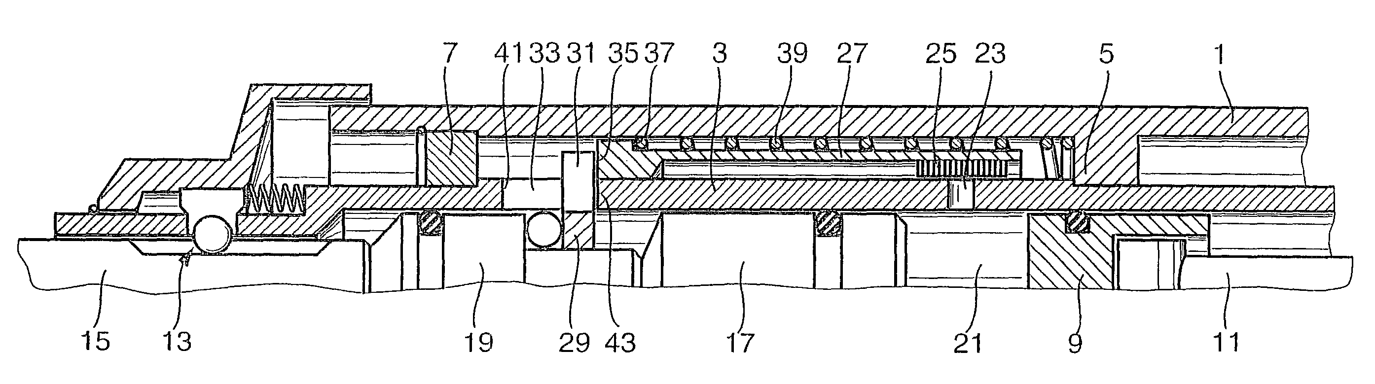
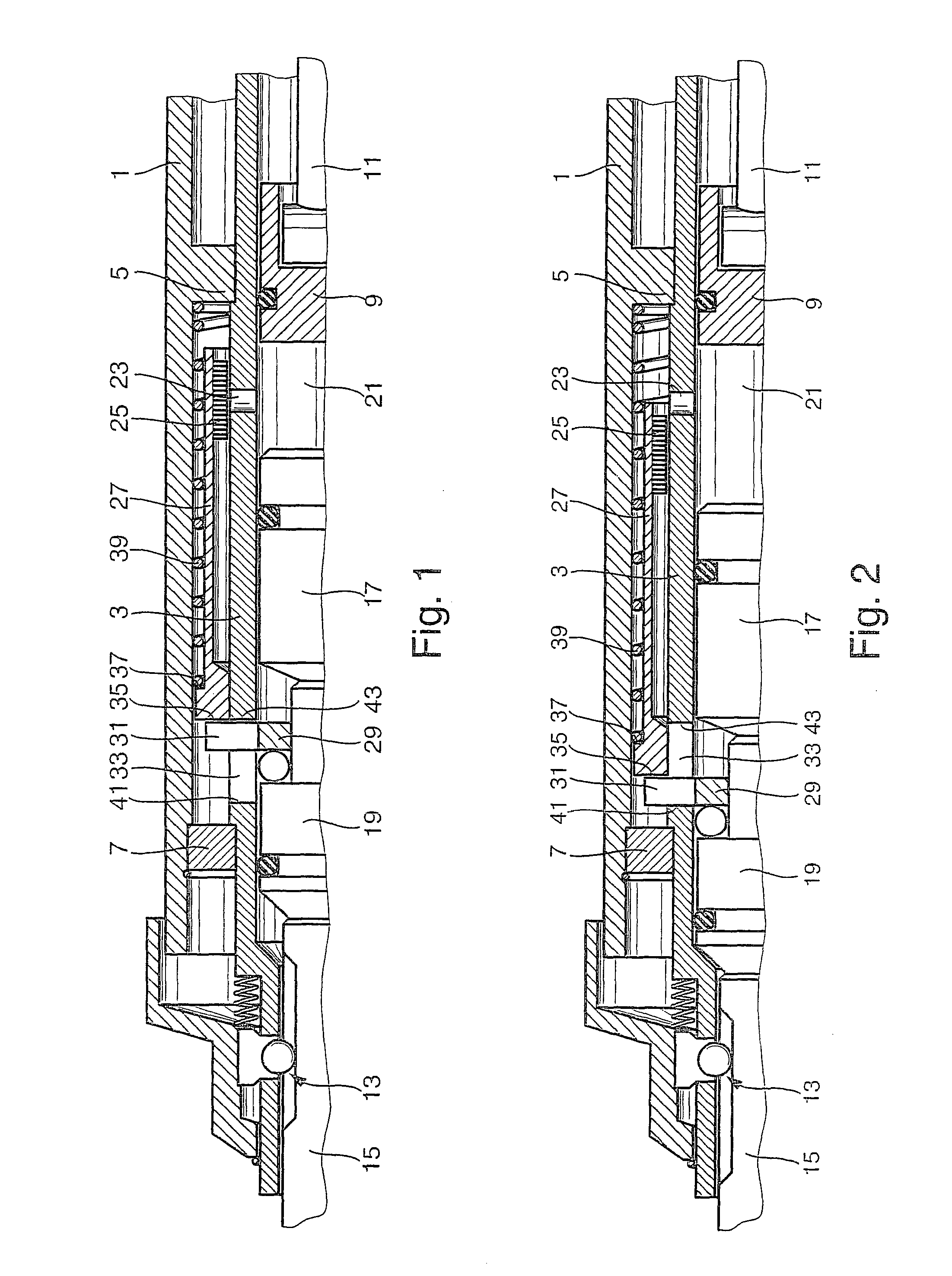
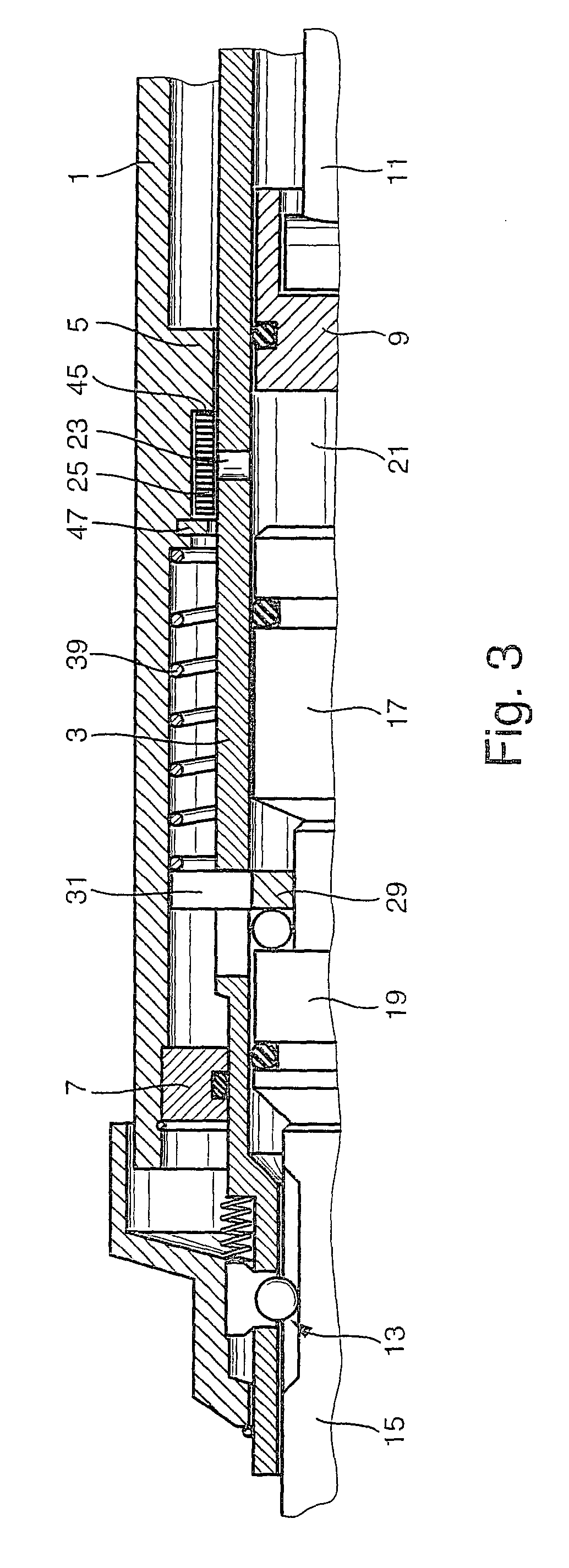
[0012]FIGS. 1 and 2 show a fragmentary longitudinal section through the striking mechanism of a drill hammer; the striking mechanism is shown in FIG. 1 in the striking position and in FIG. 2 in the idle position. The striking mechanism of this drill hammer has the following construction:

[0013]A hammer barrel 3 is rotatably supported in the power tool housing 1. Two bearing points 5 and 7 are located on the inner wall of the power tool housing 1; the bearing point 5, for instance, is an annular collar protruding integrally inward from the power tool housing 1, and the bearing point 7 is a bearing ring retained in the power tool housing 1. With its bearing points 5 and 7, the hammer barrel 3 forms a stop, so that it is not displaceable in the direction of its longitudinal axis.

[0014]A piston 9 is accommodated in the hammer barrel 3 and can be driven to reciprocate axially via a connecting rod 11. On its end remote from the piston 9, the hammer barrel 3 is provided with a tool receptac...


PUM

PropertyMeasurementUnit
axial displacementaaaaaaaaaa
restoring forceaaaaaaaaaa
pressureaaaaaaaaaa

Abstract

The striking mechanism has a hammer barrel (3), which has at least one control opening (23) through which, in an idle position, the air can escape from the hammer barrel (3), and which in a striking position is closed by a covering (25) that prevents the escape of air. To achieve the greatest possible sealing off of the at least one control opening (23) and thus high efficiency of the striking mechanism, the covering (25) is molded from an elastomer.

Description

BACKGROUND OF THE INVENTION[0001]The present invention relates to a hand power tool—preferably a drill hammer or jackhammer—with a pneumatic striking mechanism that has a hammer barrel which has at least one control opening, through which, in an idle position, air can escape from the hammer barrel and which is closed, in a striking position, by a covering preventing the escape of air.[0002]A hand power tool of this kind with a pneumatic striking mechanism is known, for instance from German Patent Disclosure DE 197 24 531 A1. In the drill hammer or jackhammer described in this reference, an axially displaceably supported hammer barrel is disposed in the power tool housing. An axially reciprocating piston is accommodated in the hammer barrel and is coupled with a striker via an air cushion. A restoring spring, with a restoring force, urges the hammer barrel in the direction of an outset position, in which the air cushion space in the hammer barrel is ventilated via a control opening, ...

Claims


Application Information

Patent Timeline
Patent Type & Authority Patents(United States)
IPC IPC(8): B23Q5/00B23B45/16B25D11/00
CPCB25D11/005B25D2250/131B25D2250/035B25D2222/57
Inventor MUELLER, FRANKMEIXNER, GERHARD
Owner ROBERT BOSCH GMBH
Why Eureka
Try Eureka