Locking device to secure a telescopic tube assembly

a technology of locking device and telescopic tube, which is applied in the direction of rod connection, coupling, machine support, etc., can solve the problems of almost impossible lone operator to finish the adjustment of the telescopic tube assembly, the operator has to struggle to hold the weight of the illuminating device, etc., and achieve the effect of safe finish

Active Publication Date: 2006-05-09
HSIEH WU HONG
View PDF11 Cites 48 Cited by
  • Summary
  • Abstract
  • Description
  • Claims
  • Application Information

AI Technical Summary

Benefits of technology

[0007]The primary objective of the present invention is to provide an improved locking device to enable a lone operator to safely finish the adjustment of the relative position of the inner tube relative to the outer tube.
[0008]Another objective of the present invention is to eliminate danger to the operator by providing a safety device to prevent excessive movement of the inner tube relative to the outer tube.

Problems solved by technology

However, when a distal end of the inner tube (41) is provided with a heavy load, i.e. an illuminating device, the operator has to struggle to hold the weight of the illuminating device.
That is, it is almost impossible for a lone operator to finish the adjustment of the telescopic tube assembly, especially when a weighty object is on top of the telescopic tube assembly.

Method used


Image

  • Locking device to secure a telescopic tube assembly
  • Locking device to secure a telescopic tube assembly
  • Locking device to secure a telescopic tube assembly

Examples


Embodiment Construction

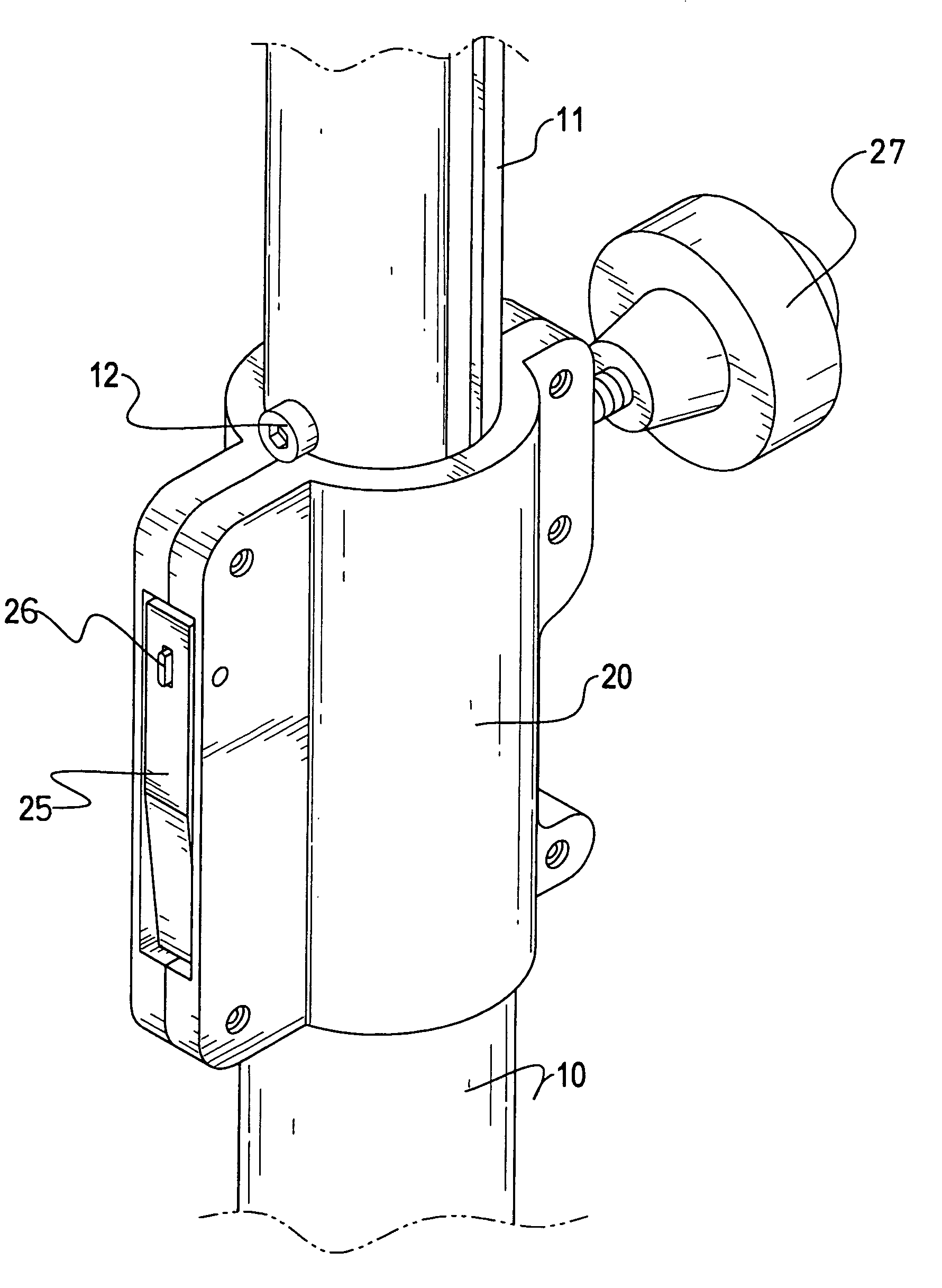
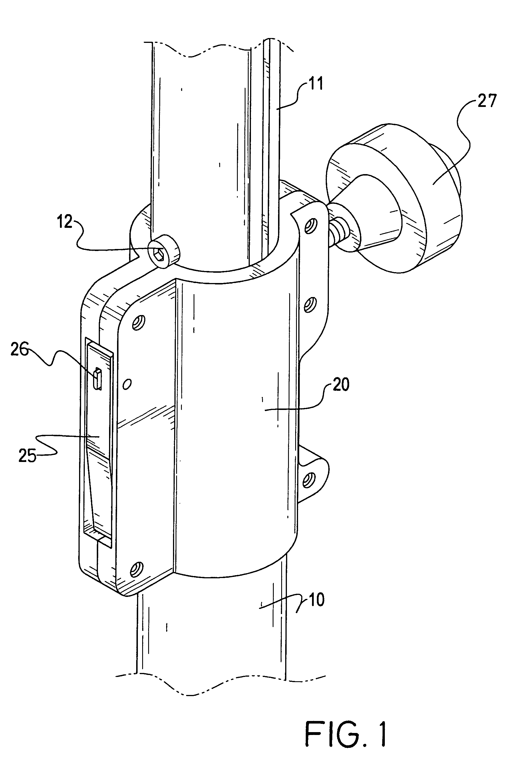
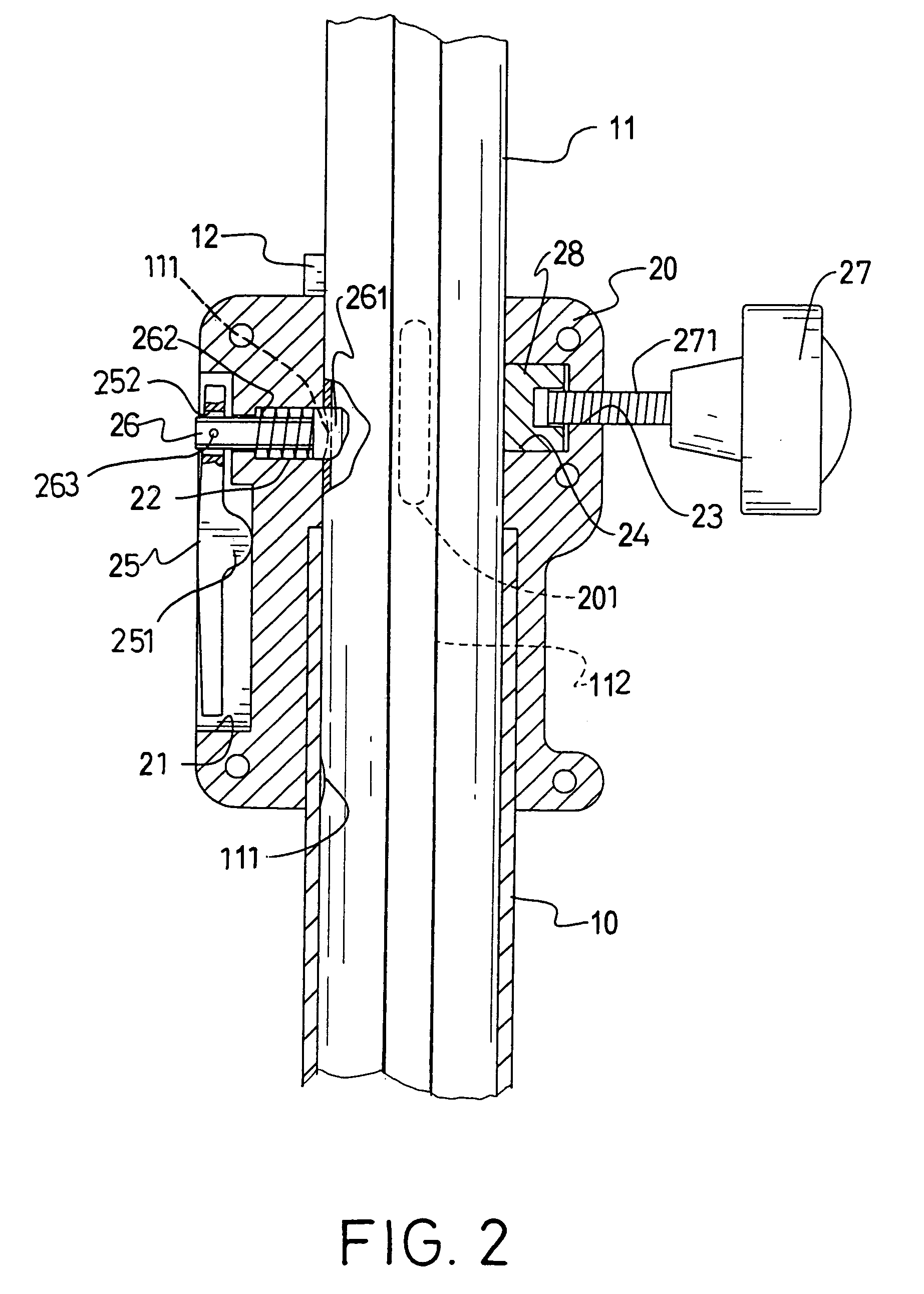
[0016]With reference to FIGS. 1 and 2, a telescopic tube assembly includes an outer tube (10) and an inner tube (11) slidably received in the outer tube (10). The inner tube (11) has multiple adjusting recesses (111) defined in an outer periphery of the inner tube (11) and a guiding groove (112) defined on the outer periphery of the inner tube (11) along a longitudinal axis of the inner tube (11).

[0017]A locking device in accordance with the present invention includes an enclosure (20) partially securely mounted on a peripheral edge of the outer tube (40) and having a guide (201) formed on an inner face of the enclosure (20), a first space (21) defined in a side face of the enclosure (20), a first hole (22) defined through a bottom face defining the first space (21), a second hole (23) defined through the enclosure (20) to be opposite to the first hole (22) and a second space (24) defined to communicate with the second hole (23).

[0018]Furthermore, a lever (25) is received in the fir...


PUM


Abstract

A locking device has an enclosure partially securely mounted on a peripheral edge of the outer tube and having a lever pivotally connected to the enclosure; and a positioning rod securely connected to a side of the lever to be driven by the lever and having a head formed on a free end of the positioning rod to correspond to one of the adjusting recesses of the inner tube such that pivotal movement of the lever is able to drive the head of the positioning rod to selectively move away from the corresponding adjusting recess to allow the inner tube to move relative to the outer tube.

Description

BACKGROUND OF THE INVENTION[0001]1. Field of the Invention[0002]The present invention relates to a locking device, and more particularly to locking device to secure an inner tube in an outer tube of a telescopic tube assembly.[0003]2. Description of Related Art[0004]With reference to FIG. 6, a conventional locking device (50) for a telescopic tube assembly having an outer tube (40) and an inner tube (41) slidably received in the outer tube (40) includes a knob (51) rotatably mounted on a side of the locking device (50).[0005]When the relative position of the inner tube (41) is to be readjusted, the operator has to hold the inner tube (41) to prevent the inner tube (41) from slipping too far into the outer tube (40). Then the operator is able to unscrew the knob (51) and change the relative position of the inner tube (41) to the outer tube (40). However, when a distal end of the inner tube (41) is provided with a heavy load, i.e. an illuminating device, the operator has to struggle t...

Claims


Application Information

Patent Timeline
Patent Type & Authority Patents(United States)
IPC IPC(8): F16B7/14F16B7/10
CPCF16B7/105Y10T403/7083Y10T403/7081Y10T403/32483Y10T403/7079Y10T403/7077Y10T403/32508
Inventor HSIEH, WU-HONG
Owner HSIEH WU HONG
Why Eureka
Try Eureka