Intraoperative endocardial and epicardial ablation probe

an endocardial and epicardial technology, applied in the field of endocardial and epicardial ablation probes, can solve the problems of requiring further ablation, difficult to accurately position and maintain the positioning of the electrode relative to a portion of myocardial tissue, and ablation or destruction of healthy tissu

Inactive Publication Date: 2006-05-09
WESTERN SYDNEY LOCAL HEALTH DISTRICT
View PDF22 Cites 82 Cited by
  • Summary
  • Abstract
  • Description
  • Claims
  • Application Information

AI Technical Summary

Benefits of technology

[0044]ablating said tissue using one or mor

Problems solved by technology

A significant disadvantage of conventional catheter ablation is that, due to the very flexible nature of the catheter itself, it is difficult to accurately position and maintain the positioning of the electrodes relative to a portion of myocardial tissue.
This is disadvantageous in that movement and imprecise placement of the catheter can result undesirably in the ablation or destruction of healthy tissue, while at the same time the tissue sought-to-be ablated may not have been ablated, thereby requiring further ablation.
As will be understood from FIG. 2, due to the readily flexible nature of the catheter body 14 and its limited ability to retain any particular form, the catheter 10 is difficult to position at a desired location, and often does not adequately conform to the tissue surface.
Another disadvantage of such catheter probes 10 is that

Method used


Image

  • Intraoperative endocardial and epicardial ablation probe
  • Intraoperative endocardial and epicardial ablation probe
  • Intraoperative endocardial and epicardial ablation probe

Examples


first embodiment

USE OF THE FIRST EMBODIMENT

[0069]FIGS. 7A to 7D illustrate an exemplary use of the malleable ablation probe 38, 40 to produce linear lesions. To septate an interior surface of the right atrium 96, a small cut 94 is made into the myocardial tissue. A surgeon then illuminates the aperture using a light 92 and observes the interior surfaces of the chamber. Having observed the surface to be ablated, the surgeon shapes, bends or otherwise deforms the RF ablation probe 38, 40 so that the malleable tip containing the electrodes 40 conforms with the surface to be ablated. The surgeon can test fit the tip and remove it for minor shape adjustments until a satisfactorily complementary fit is achieved between the tip electrodes and the tissue surface.

[0070]FIG. 7B illustrates a reverse “S” shape formed by the RF ablation probe 38, which is inserted via the aperture 94 into the atrium 96. The upper surface of the probe 38 containing the electrodes 40 is bent to conform with the contoured inner s...

second embodiment

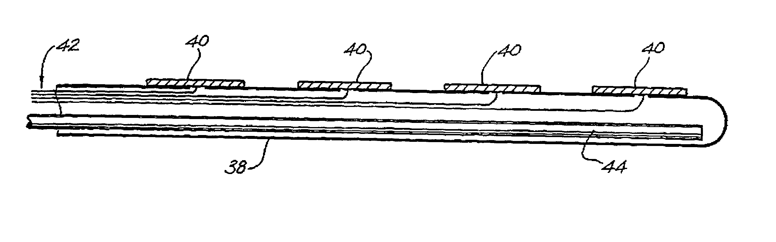
[0072]FIGS. 8 to 10 illustrate side elevation, top plan and cross-sectional front elevation views of an RF ablation probe according to the second embodiment of the invention. The RF ablation probe 60 comprises a hollow, substantially tubular body 58 made of teflon plastic, a number of flat, conductive electrodes 50, and a malleable core 54 (not shown in FIGS. 8 and 9) contained within the centre of the thermally and electrically insulative body 58. In particular, the teflon body 58 has a relatively rigid yet bendable structure and is capable of being permanently formed to have a particular shape. As indicated in FIG. 8, the upper surface of the distal end of the tubular body 58 is crimped to produce a flat surface. The electrodes 50 are arranged on the flat upper surface, and again are separated by thermally and electrically insulative material.

[0073]The electrodes 50 have a like construction to those described hereinbefore with reference to the first embodiment. The flat upper surf...

third embodiment

[0077]FIGS. 11 to 13 illustrate an RF ablation probe 70 according to a third embodiment of the invention. Again, a number of flat electrodes 80 are arranged at predetermined spaces on a top surface of an elongate probe body 82. The body of 82 of the probe is tubular and preferably made of a rubber or soft plastic materials, such as SILASTIC, which is thermally and electrically insulative. Electrical conductors or leads connected to each electrode 80 are not shown in FIGS. 11 to 12 to simplify the diagram.

[0078]In this embodiment, rather than having an internal malleable core, a rigid, pre-formed or shaped insert member 84 is inserted into the internal cavity of the tubular body 82 at its distal end to thereby give the probe 70 a corresponding pre-formed shape. The insert member 84 in this example has an S-shape. In FIGS. 11 and 13, the pre-formed, rigid, cylindrical insert member 84 is preferably made of stainless steel or a rigid plastic body and can be inserted into the interior c...


PUM


Abstract

An elongate, malleable ablation probe including an elongate malleable body (38) and a plurality of longitudinally spaced apart electrodes (40) disposed at a distal end thereof. The electrodes (40) are separated one from another by insulative material. In one embodiment, a malleable insert is provided for insertion into a flexible longitudinal sleeve, the flexible longitudinal sleeve conforming to the shape of the malleable insert upon such insertion. In other embodiments, a malleable core is surrounded by a flexible body, the electrodes (40) being mounted to the body.

Description

[0001]The application is a divisional of application Ser. No. 09 / 485,361, filed Dec. 14, 2000, now U.S. Pat. No. 6,540,742 which is a 371 of PCT / AU98 / 00590, filed Jul. 24, 1998, which application(s) are incorporated herein by reference.[0002]The present invention relates to a method and apparatus for mapping and ablating tissue, and in particular to a malleable, shapeable probe for producing elongated linear lesions in tissue.BACKGROUND[0003]It is known that tissue, including damaged myocardial tissue, can be ablated by the application of radio frequency energy thereto via conductive electrodes embodied in a probe structure. RF ablation of tissue is commonly used in an attempt to remove myocardial defects, tumours, portions of tissue mass, and the like. RF ablation can be used to treat cardial disfunctions such as ventricular arrhythmia, atrial flutter, atrial fibrillation, ventricular tachycardia and the like.[0004]Such disorders involve abnormal heart muscles causing abnormal acti...

Claims


Application Information

Patent Timeline
IPC IPC(8): A61B18/14A61B17/00A61M25/01A61N1/05A61N1/06
CPCA61B17/00234A61N1/06A61B18/1402A61B18/1492A61B2017/00088A61B2017/00101A61B2017/00243A61B2018/0016A61B2018/00214A61B2018/00351A61B2018/00791A61B2018/00797A61B2018/00815A61B2018/00821A61B2018/00839A61B2018/00898
Inventor THOMAS, STUARTROSS, DAVIDREES, ARIANWENPATTERSON, ROBERTDALY, MICHAELKOEVSKI, ILIJA
Owner WESTERN SYDNEY LOCAL HEALTH DISTRICT
Why Eureka
Try Eureka