Epicardial ablation catheter

a catheter and epidermis technology, applied in the field of epidermis ablation catheters, can solve the problems of unmet needs, local gaps or pores in the cell membrane, occurrence of local gaps or pores, etc., and achieve the effect of increasing contact and reducing the size of the adjustable loop

Active Publication Date: 2021-06-01
BOSTON SCI SCIMED INC
View PDF733 Cites 2 Cited by
  • Summary
  • Abstract
  • Description
  • Claims
  • Application Information

AI Technical Summary

Benefits of technology

[0012]In some embodiments, a method may comprise advancing a distal end of an ablation device through a first lumen of a cinch device in a proximal-to-distal direction. The ablation device may be positioned around cardiac tissue of a heart of a subject such that the ablation device forms an adjustable loop that circles around a set of pulmonary veins of the heart. The distal end of the ablation device may be advanced through a second lumen of the cinch device in a distal-to-proximal direction. The second lumen may extend substantially parallel to the first lumen. At least one of the distal end or a proximal end of the ablation device may be moved proximally from a proximal end of the cinch device to reduce a size of the adjustable loop and increase contact between the ablation device and the cardiac tissue.

Problems solved by technology

While the precise mechanism of this electrically-driven pore generation or electroporation continues to be studied, it is thought that the application of relatively brief and large electric fields generates instabilities in the lipid bilayers in cell membranes, causing the occurrence of a distribution of local gaps or pores in the cell membrane.
While pulsed DC voltages may drive electroporation under the right circumstances, there remains an unmet need for thin, flexible, atraumatic devices that effectively deliver high DC voltage electroporation ablation therapy selectively to cardiac tissue in regions of interest.

Method used


Image

  • Epicardial ablation catheter
  • Epicardial ablation catheter
  • Epicardial ablation catheter

Examples


Embodiment Construction

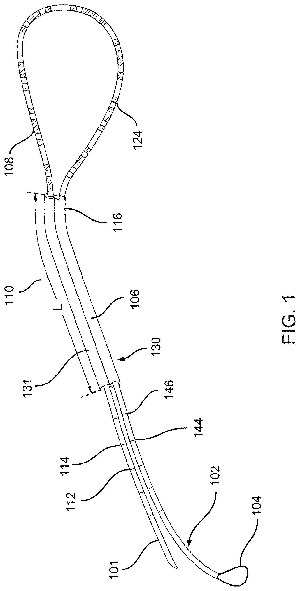
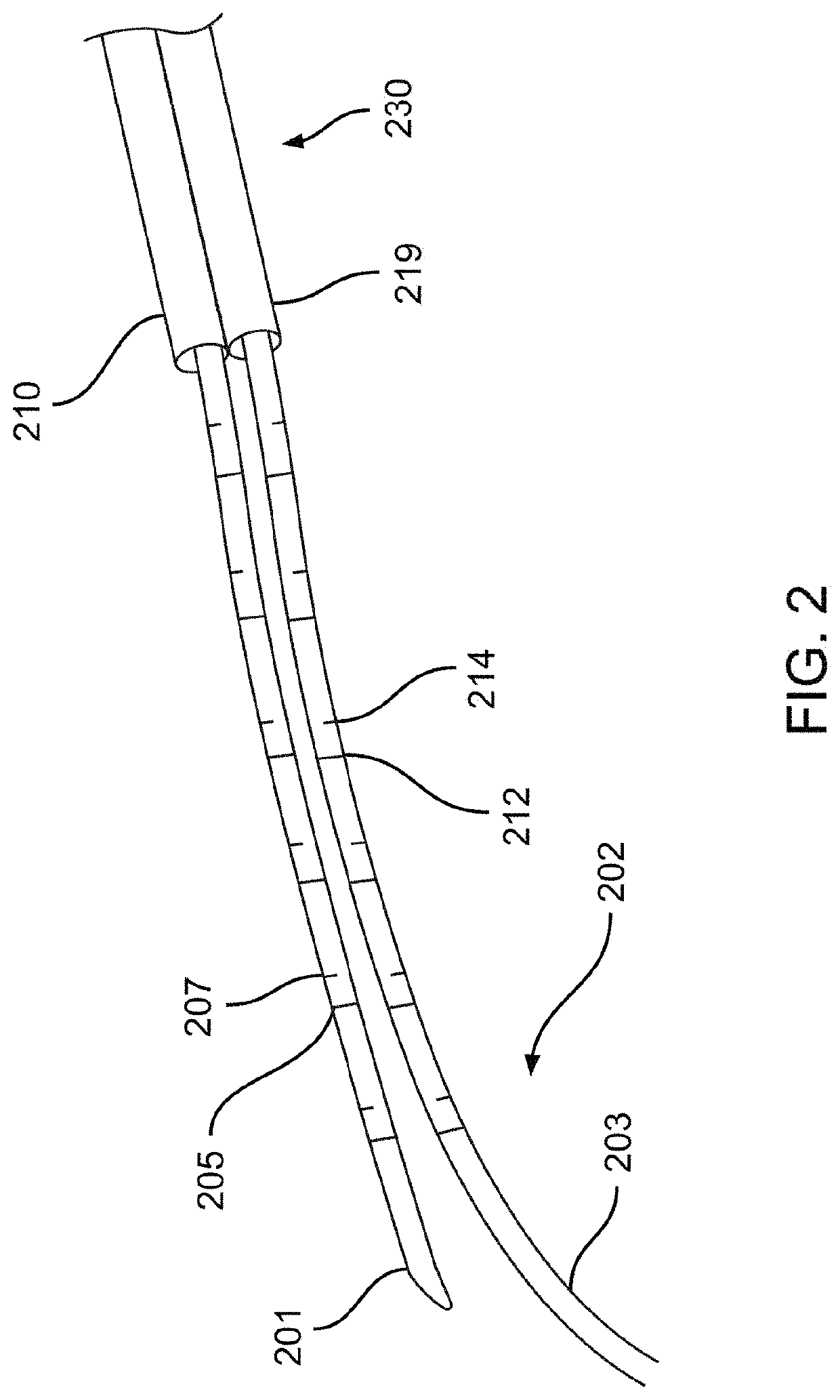
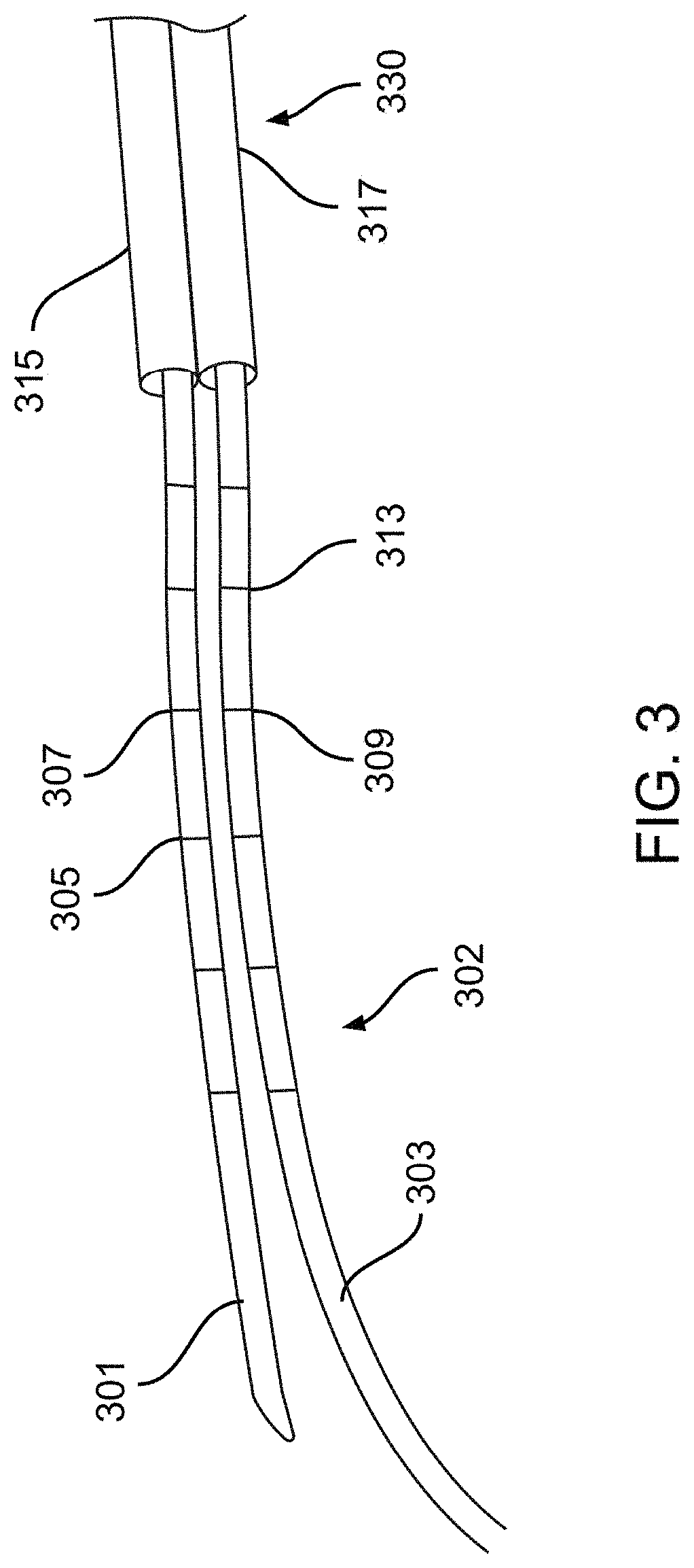
[0033]Described herein are systems, devices, and methods for selective and rapid application of pulsed electric fields to ablate tissue by irreversible electroporation. Generally, the systems, devices, and methods described herein may be used to generate large electric field magnitudes at desired regions of interest and reduce peak electric field values elsewhere in order to reduce unintended tissue damage. The devices described herein include flexible catheters that may be placed for pulsed electric field ablation of cardiac tissue. In some embodiments, an ablation device may be placed via subxiphoid access or by direct surgical placement into the pericardial space. Proper physical placement and tension applied between an ablation device (e.g., ablation catheter) and tissue to be ablated may ensure targeted and effective electroporation with reduced side effects and user error. For example, a cinch device and fiducials disposed thereon may be used to aid in positioning and verifica...


PUM


Abstract

Systems, devices, and methods for electroporation ablation therapy are disclosed herein, with a cinch device for positioning an ablation catheter relative to tissue during a cardiac ablation procedure. In some embodiments, a distal end of a first device may be advanced into a proximal end of a first lumen of a second device. The first device may be advanced from a distal end of the first lumen and the first device may be looped around tissue of a patient. The first device may be advanced into a distal end of a second lumen of the second device. The distal end of the first device may be advanced from a proximal end of the second lumen. The proximal and distal ends of the first device may be advanced away from a proximal end of the second device to increase contact between the first device and the tissue.

Description

CROSS-REFERENCE TO RELATED APPLICATIONS[0001]This application is a continuation of International Application No. PCT / US2019 / 030882, filed on May 6, 2019, which claims the benefit of U.S. Provisional Application No. 62 / 667,964, filed on May 7, 2018, the entire disclosure of each of which is incorporated herein by reference in its entirety.BACKGROUND[0002]The generation of pulsed electric fields for tissue therapeutics has moved from the laboratory to clinical applications over the past two decades, while the effects of brief pulses of high voltages and large electric fields on tissue have been investigated for the past forty years or more. Application of brief high direct current (DC) voltages to tissue may generate locally high electric fields typically in the range of hundreds of volts per centimeter that disrupt cell membranes by generating pores in the cell membrane. While the precise mechanism of this electrically-driven pore generation or electroporation continues to be studied...

Claims


Application Information

Patent Timeline
Patent Type & Authority Patents(United States)
IPC IPC(8): A61B18/18A61B18/14A61B18/00
CPCA61B18/1492A61B2018/00166A61B2018/00363A61B2018/00375A61B2018/00577A61B2018/00613A61B2018/1407A61B2018/1467A61B2018/1497A61B2018/00351
Inventor VISWANATHAN, RAJUPAGEARD, JEAN-LUC
Owner BOSTON SCI SCIMED INC
Why Eureka
Try Eureka