
Non-intrusive inspection impulse radar antenna

a radar antenna and impulse technology, applied in the direction of electromagnetic wave detection, measurement devices, instruments, etc., can solve the problems of unfavorable reflection between the antenna and the ground or other objects, interference referred to as “clutter”, etc., and achieve the effect of linear increase of resistivity per unit length with distance from the feed

Active Publication Date: 2006-05-09
NIITEK
View PDF5 Cites 60 Cited by
  • Summary
  • Abstract
  • Description
  • Claims
  • Application Information

AI Technical Summary

Benefits of technology

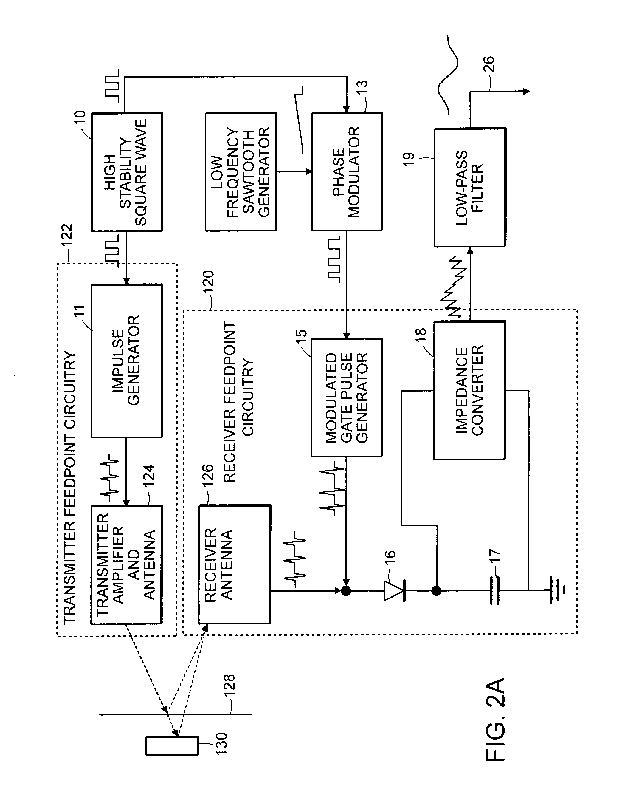
[0014]In accordance with yet other embodiments of the invention, a receiver is provided for an impulse radar system that is characterized by a strobe pulse. The receiver has a broadband antenna having a feed, and a low-radar cross-section front-end module coupled directly to the feed of the antenna. The front-end module includes only a pulse former, a receiving diode, an integrating element, and a impedance matching element. The receiver has a transmission line having a prox...

Problems solved by technology

However, when the antenna is located near the ground or other objects, undesired reflections may appear between the antenna and the ground or other objects.
Multiple reflections result in interference referred to as “clutter”.

Method used


Image

  • Non-intrusive inspection impulse radar antenna
  • Non-intrusive inspection impulse radar antenna
  • Non-intrusive inspection impulse radar antenna

Examples


Embodiment Construction

[0022]The problem of multiple reflection clutter-signals, discussed above, is advantageously reduced, in accordance with embodiments of the present invention, by employing antennas having a low radar cross-section, ideally a radar cross section of zero. In accordance with the present invention, a low radar cross section is achieved while retaining an effective search capacity. The antenna's advantages additionally include its cost-effectiveness and its reduced use of materials and production capacity.

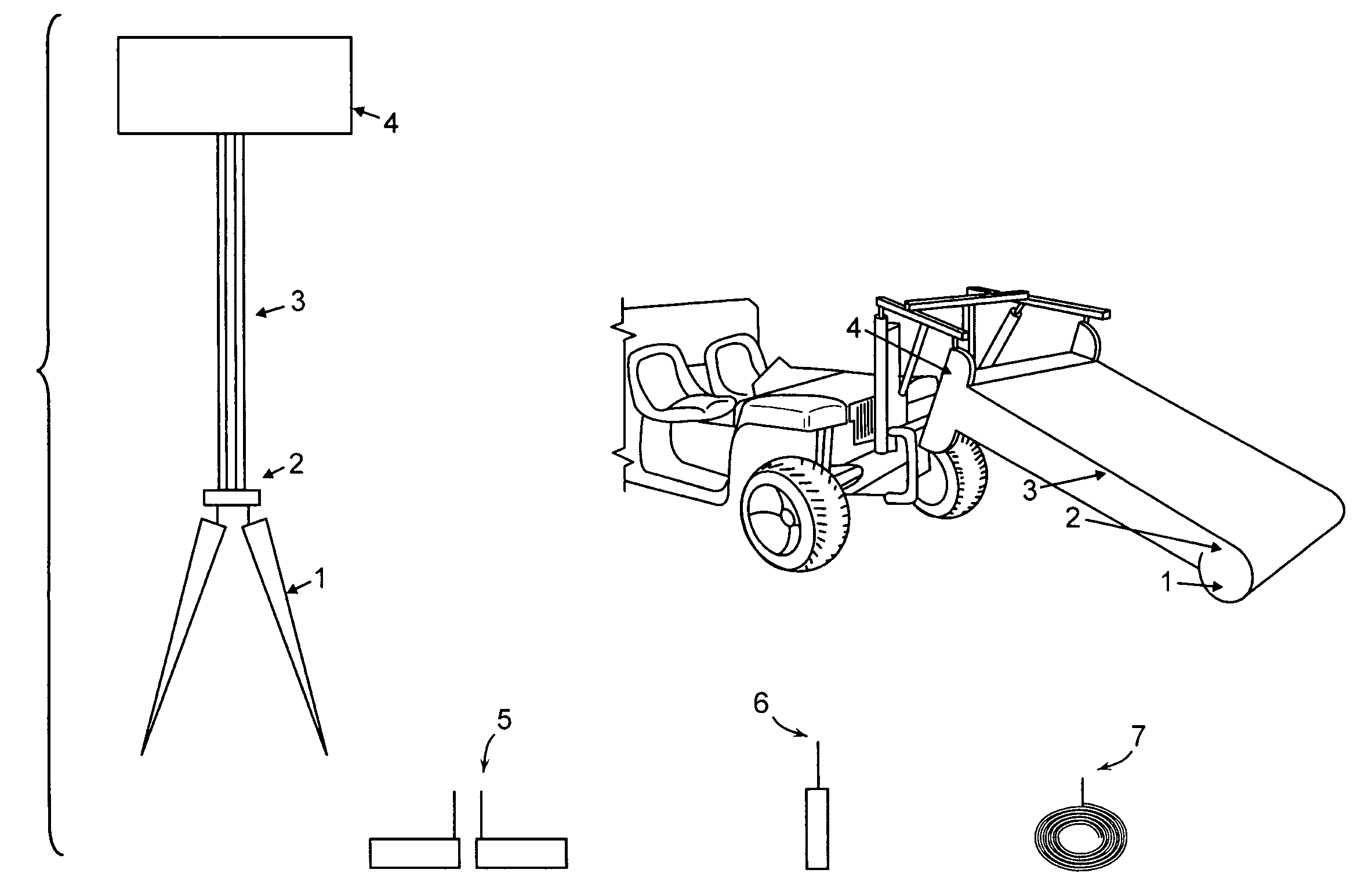
[0023]In accordance with embodiments of the present invention, highly resistive, low-metal-content, antenna arms are employed, as now described with reference to FIG. 1. In preferred embodiments of the invention, a resistive tapered-Vee antenna 1, characterized by low metal content, is employed. In preferred embodiments of the invention, the impedance of the antenna is governed by the deposition, typically by sputtering, of a thin film of conductor, such as gold. This process is preferr...


PUM

PropertyMeasurementUnit
Timeaaaaaaaaaa
Strengthaaaaaaaaaa
Electrical resistivityaaaaaaaaaa

Abstract

An apparatus and method for detecting objects buried beneath the surface of a medium. A plurality of wide-bandwidth antennas, coupled to form an array, is drawn across the surface. Each antenna radiates a plurality of pulses of electromagnetic radiation at periodic intervals of time and receives the plurality of pulses after their interaction with the medium. The return pulses are sampled by a sampling circuit disposed at the feed of each antenna so as to create an equivalent-time pulse signal, and a self-signature of each antenna is subtracted from the equivalent-time pulse signal so as to detect features of objects buried beneath the surface of the medium. A pulse former is provided at the feedpoint of the receiving antenna.

Description

TECHNICAL FIELD[0001]The present invention pertains to a high-bandwidth and high-frequency non-intrusive inspection radar system, and, more particularly, to a radar system having features providing for a low self-signature, referred to, herein, as a low radar cross section (LRC).BACKGROUND ART[0002]Very high-frequency emitting radar antennas have been used in the detection of land mines or other concealed objects. As used herein, the term ‘very high frequency’ refers to radar systems employing at least some frequency components in a range in excess of 30 MHz. Moreover, while radar systems, and the invention described herein, may advantageously be employed for a wide variety of non-intrusive inspection (NII) applications, including, without limitation, narcotics detection, bomb detection, buried cable and pipe detection, motion detection, corpse detection, see-through-the wall technology, archaeology, geophysics, etc., the invention is described, herein, in terms of a ground-penetrat...

Claims


Application Information

Patent Timeline
IPC IPC(8): G01S13/88
CPCG01S13/885G01S13/888G01V3/12G01S13/04Y10T29/49002Y10T29/49018Y10T29/49016
Inventor WICHMANN, GUNTER
Owner NIITEK
Learn More