Dual band, low profile omnidirectional antenna

a low-profile, antenna technology, applied in the direction of antennas, antenna details, antenna earthings, etc., can solve the problems of large patch antennas, inconvenient terrestrial communication, and expensive and aesthetically disconcerting the installation of several antennas on a vehicl

Inactive Publication Date: 2006-05-09
GM GLOBAL TECH OPERATIONS LLC
View PDF14 Cites 269 Cited by
  • Summary
  • Abstract
  • Description
  • Claims
  • Application Information

AI Technical Summary

Problems solved by technology

Providing several antennas on a vehicle is costly and aesthetically displeasing.
However, the patch antenna transmits / receives most of its energy perpendicular to the plane of the patch antenna, which is not suitable for terrestrial communications.
Additionally, patch antennas are large in size, which is costly and aesthetically displeasing.
While the dual band PIFA transmits / receives vertical polarized signals at both frequencies, the separation between the available frequencies is not suitable for communication in both the AMPS and PCS bands.

Method used


Image

  • Dual band, low profile omnidirectional antenna
  • Dual band, low profile omnidirectional antenna
  • Dual band, low profile omnidirectional antenna

Examples


Embodiment Construction

[0024]The following description of the preferred embodiment(s) is merely exemplary in nature and is in no way intended to limit the invention, its application, or uses. For purposes of clarity, the same reference numbers will be used in the drawings to identify similar elements.

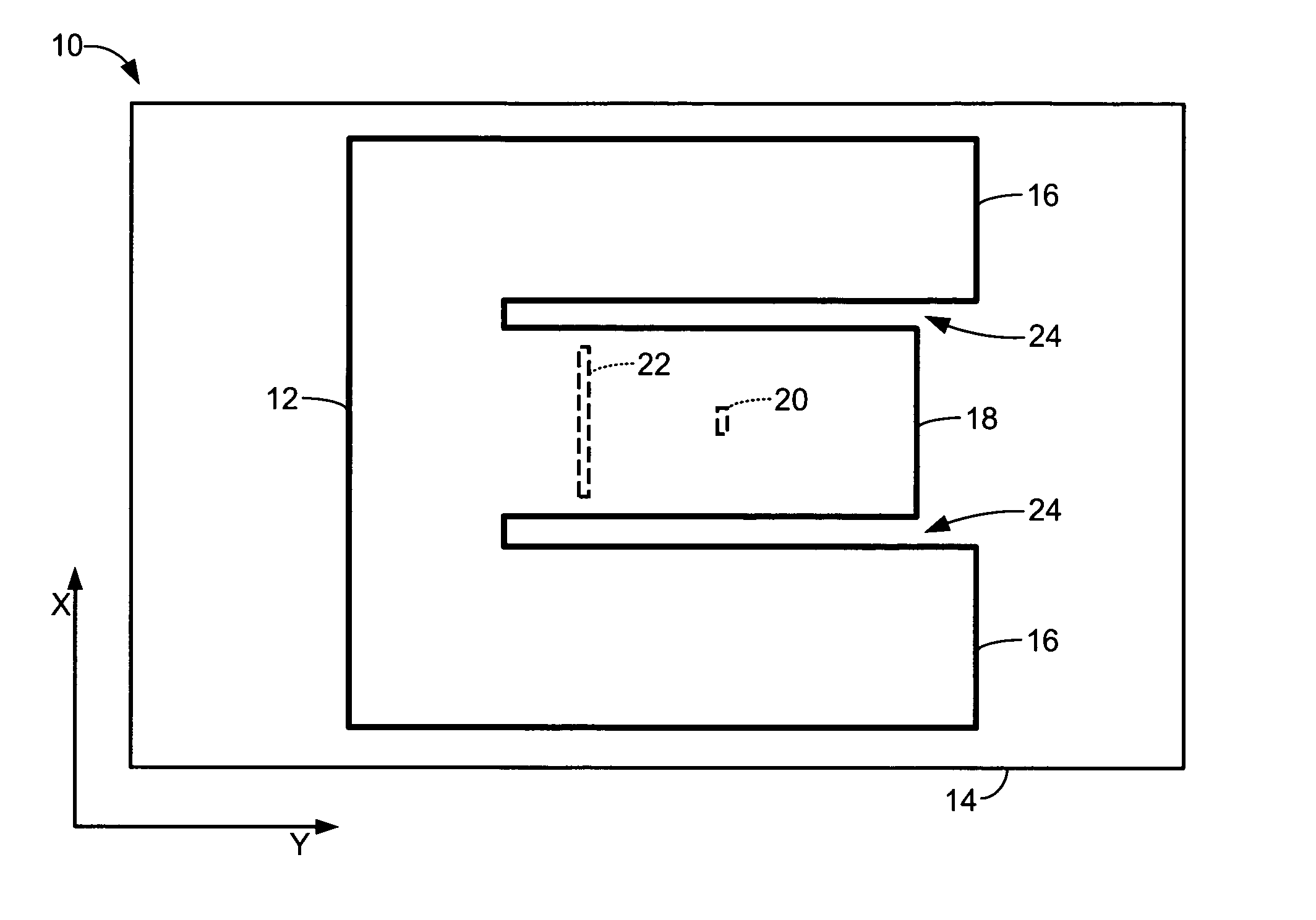
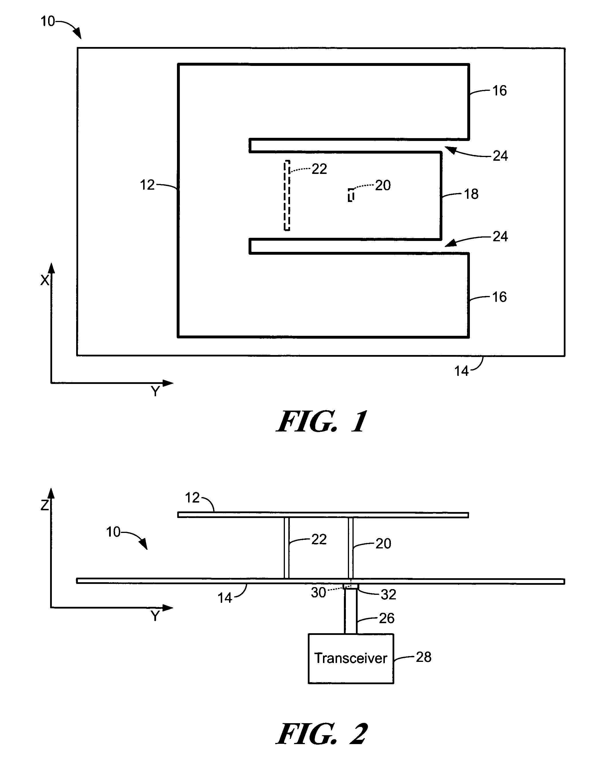
[0025]Referring to FIGS. 1 and 2, an antenna 10 includes a metal plate 12 that is located a first distance from a ground plane 14. The metal plate 12 is E-shaped and includes first and second outer extensions 16 and an inner extension 18. A feed tab 20 and a shorting tab 22 are connected between the inner extension 18 and the ground plane 14.

[0026]The antenna 10 is a combination of an inductively loaded center fed patch antenna and a Planar Inverted-F Antenna (PIFA). Center fed patch antennas typically include a feed tab located in the center of a metal plate. Center fed patch antennas are inductively loaded by positioning two shorting tabs on each side of a feed tab. For example, an article by C. Delaveaud, ...


PUM


Abstract

A low-profile dual-band antenna includes a ground plane. An “E”-shaped metal plate is located a first distance from the ground plane and includes first and second outer extensions and an inner extension of the metal plate. A feed tab connects the inner extension and the ground plane. A shorting tab connects the inner extension and the ground plane. The low-profile dual-band antenna communicates first radio frequency (RF) signals in a first RF band and second RF signals in a second RF band. The first RF signals and the second RF signals are vertical polarized signals. The low-profile dual-band antenna produces a radiation pattern that is omnidirectional in the azimuth plane and vertically polarized in a horizontal plane when communicating the first RF signals and the second RF signals. The first RF band and the second RF band can be independently tuned.

Description

FIELD OF THE INVENTION[0001]The present invention relates to low-profile antennas, and more particularly to dual-band low-profile antennas.BACKGROUND OF THE INVENTION[0002]Various vehicle systems may require an antenna for mobile phones, satellite radio, terrestrial radio, and / or global positioning systems. Providing several antennas on a vehicle is costly and aesthetically displeasing. The antennas are preferably low profile and small in size.[0003]Most Terrestrial communications systems require the transmission and / or reception of vertical polarized signals. Terrestrial communications systems may require reception and transmission of radio frequency (RF) signals in multiple bands. For example, vehicle systems such as mobile phones and remote assistance services transmit and / or receive vertical polarized signals in multiple bands.[0004]Mobile phone and remote assistance services typically require communication in both the Advanced Mobile Phone System (AMPS) and the Personal Communi...

Claims


Application Information

Patent Timeline
Patent Type & Authority Patents(United States)
IPC IPC(8): H01Q1/24H01Q1/48H01Q5/00H01Q5/357H01Q9/04
CPCH01Q1/243H01Q5/357H01Q9/0442H01Q9/0421
Inventor COLBURN, JOSEPH S.SIEVENPIPER, DANIEL F.
Owner GM GLOBAL TECH OPERATIONS LLC
Why Eureka
Try Eureka