Enhancements to optical flat panel displays

a flat panel display and flat panel technology, applied in the field of flat panel displays, can solve the problems of large number of top and bottom plates not being able to coincide geometrically, difficult to achieve the discrete top and bottom capacitor plates, and increasing difficulty in achieving them. to achieve the effect of expanding the color pal

Inactive Publication Date: 2006-05-09
RAMBUS DELAWARE
View PDF3 Cites 66 Cited by
  • Summary
  • Abstract
  • Description
  • Claims
  • Application Information

AI Technical Summary

Benefits of technology

[0033]In another embodiment of the present invention, a method for extending a color palette may comprise the step of subdividing a primary color into n divisions resulting in n+1 intensities for the primary color. The method may further comprise adding m additional subdivisions to the primary color. The method may further comprise adjusting the intensity of a plurality of lamps during a first m subdivisions of the primary color resulting in the plurality of lamps operating at 1 / (m+1) intensity during the first m subdivisions and adding one or more binary bits of information to the primary color to extend the color palette.

Problems solved by technology

Over large areas, registration (the term given to the optical alignment and geometric coincidence of complementary device components topologically disposed on either consecutive or nonconsecutive parallel planes in spaced-apart relation) between the discrete top and bottom capacitor plates becomes progressively more difficult to achieve, until the registration error is multiplied to the point that a large number of top and bottom plates no longer adequately register.
That is, the top and bottom plates fail to coincide geometrically due to differential dimensional drift incurred during fabrication and / or assembly of the respective laminae on which the discrete elements are disposed.
Consequently, the gamut of color reproduced on the display is limited.
Furthermore, infrared and other non-visible light displays are generally not integrated into an existing full color RGB display.
Furthermore, there are various approaches to the problem of efficiently encoding information displayed on a field sequential color display.
However, using this method of U.S. Pat. No. 5,319,491 results in a limited palette size.
Preventing voids in MEMS devices from being filled with the next deposition layer is difficult One method of attempting to prevent voids in MEMS devices from being filled with the next deposition layer is to deposit sacrificial layers of special material in the void.
Creating standoff structures in the MEMS industry involves complicated multi-layer work, where all manners of multiple sub-steps and invocation of so-called “sacrificial” layers is required.
These “air gaps” are often the key to many MEMS-based devices, but their fabrication remains a complicated process.
In systems such as the Frustrated Total Internal Reflection Display System disclosed in U.S. Pat. No. 5,319,491, this requirement becomes more acute in light of the larger area covered by highly detailed MEMS structures, which become increasingly susceptible to misregistration effects during fabrication.

Method used


Image

  • Enhancements to optical flat panel displays
  • Enhancements to optical flat panel displays
  • Enhancements to optical flat panel displays

Examples


Embodiment Construction

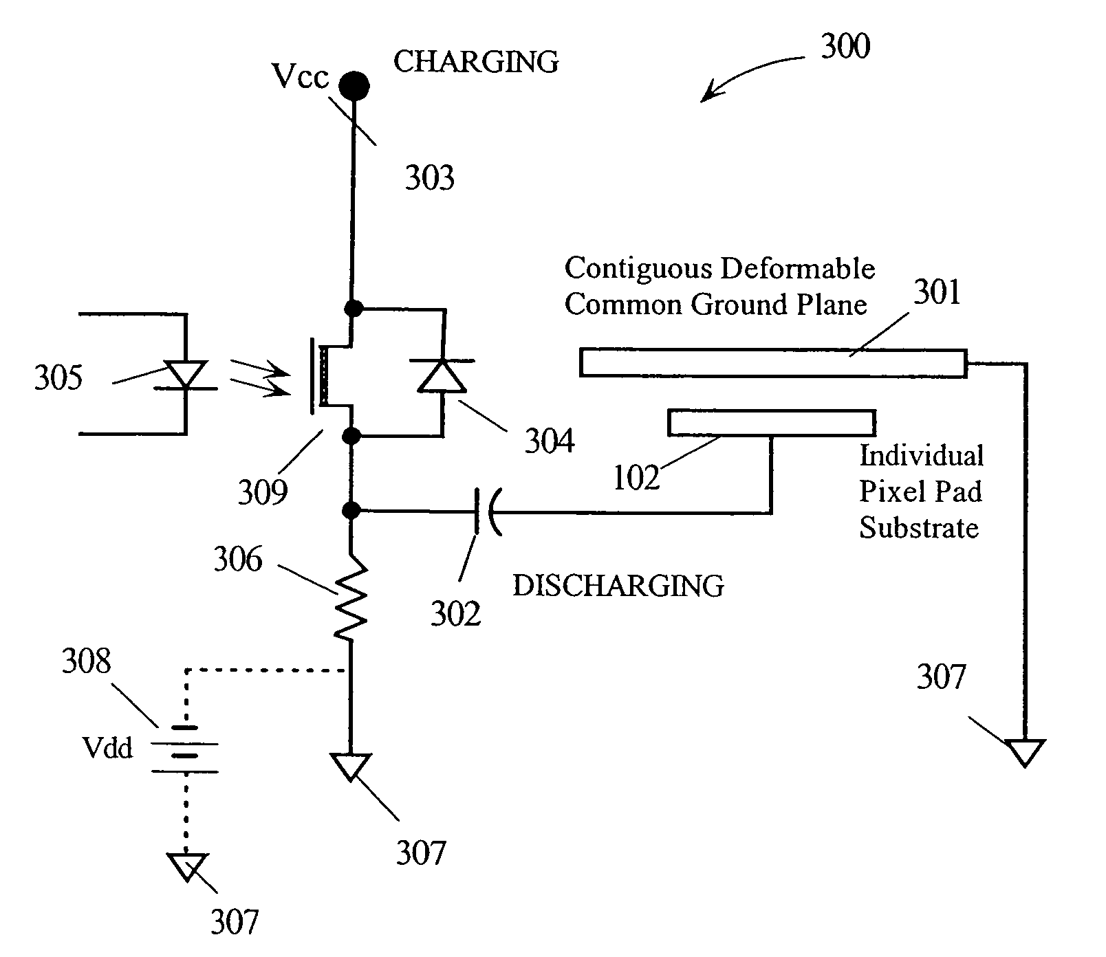
[0054]The present invention comprises a circuit to implement a registration-free, contiguous conductive plate that is itself flexible and capable of plate bending motion. In one embodiment of the present invention, a circuit may comprise a plurality of conductive structures in a first plane. The circuit may further comprise a contiguous conductive equipotential surface in a second plane parallel to the first plane. The circuit may further comprise activation means configured to adjust an electric field between the first and second planes thereby activating one or more structures in the first plane by increasing a potential difference between the first and second planes to a threshold level deemed to constitute an active state. The circuit may further comprise deactivation means configured to adjust the electric field between the first and second planes thereby deactivating one or more structures in the first plane by decreasing the potential difference between the first and second p...


PUM


Abstract

A circuit for implementing a registration-free, contiguous conductive plane. A circuit may include a plurality of conductive structures in a first plane. The circuit may further include a contiguous conductive equipotential surface in a second plane parallel to the first plane. The circuit may further include activation means configured to adjust an electric field between the first and second planes thereby activating one or more structures in the first plane by increasing a potential difference between the first and second planes to a threshold level deemed to constitute an active state. The circuit may further include deactivation means configured to adjust the electric field between the first and second planes thereby deactivating one or more structures in the first plane by decreasing the potential difference between the first and second planes below a threshold level deemed to constitute a deactivation state.

Description

CROSS REFERENCE TO RELATED APPLICATIONS[0001]This application is a 371 National Phase of International Application No. PCT / US2003 / 005736 filed on 26 Feb. 2003, which claims priority to the following U.S. patent applications:[0002]Ser. No. 60 / 359,783 filed Feb. 26, 2002, Ser. No. 60 / 359,777 filed Feb. 26, 2002, Ser. No. 60 / 359,755 filed Feb. 26, 2002, Ser. No. 60 / 359,766 filed Feb. 26, 2002, Ser. No. 60 / 359,601 filed Feb. 26, 2002, and Ser. No. 60 / 359,600 filed Feb. 26, 2002.[0003]This application is related to the following commonly owned copending U.S. patent applications:[0004]U.S. Provisional Application Ser. No. 60 / 359,783, “Field Sequential Color Palette Enhancement”, filed Feb. 26, 2002, and claims the benefit of its earlier filing date under 35 U.S.C. 119(e); and[0005]U.S. Provisional Application Ser. No. 60 / 359,777, “Airgap Autogenesis Mechanism”, filed Feb. 26, 2002, and claims the benefit of its earlier filing date under 35 U.S.C. 119(e); and[0006]U.S. Provisional Applicat...

Claims


Application Information

Patent Timeline
Patent Type & Authority Patents(United States)
IPC IPC(8): G02B26/00G02B26/02G09G3/20G09G3/34
CPCG02B26/02H04N9/3197G09G3/3413G09G3/3433H04N9/315G06F3/0421G06F2203/04109G09G3/2018G09G3/2025G09G3/2081G09G2300/0842G09G2310/0235G09G2320/0633G09G2360/142G09G2360/148G02B26/00G09G3/02
Inventor SELBREDE, MARTIN G.ESSMAN, LYNNVAN OSTRAND, DANDERICHS, KEVIN
Owner RAMBUS DELAWARE
Why Eureka
Try Eureka