Information recording medium, recording apparatus, reproduction apparatus, recording method, reproduction method and defect management method

Active Publication Date: 2006-05-09
PANASONIC CORP
View PDF5 Cites 121 Cited by
  • Summary
  • Abstract
  • Description
  • Claims
  • Application Information

AI Technical Summary

Benefits of technology

[0036]Thus, the invention described herein makes possible the advantages of providing a highly reliable information recording medium having defect management information areas located so as to face each other regardless of the recording density and allowing defects thereof to be managed by a fixed def

Problems solved by technology

The reasons for this are: (i) the defect management information itself cannot be a target of defect management; and therefore, if the defect management information area, in which the defect management information is to be recorded, has a defect area, the defect management information recorded on the information recording medium cannot be reproduced; and (ii) if the defect management information is lost, the user data recorded on the information recording

Method used


Image

  • Information recording medium, recording apparatus, reproduction apparatus, recording method, reproduction method and defect management method
  • Information recording medium, recording apparatus, reproduction apparatus, recording method, reproduction method and defect management method
  • Information recording medium, recording apparatus, reproduction apparatus, recording method, reproduction method and defect management method

Examples


example 1

(1) Information Recording Medium

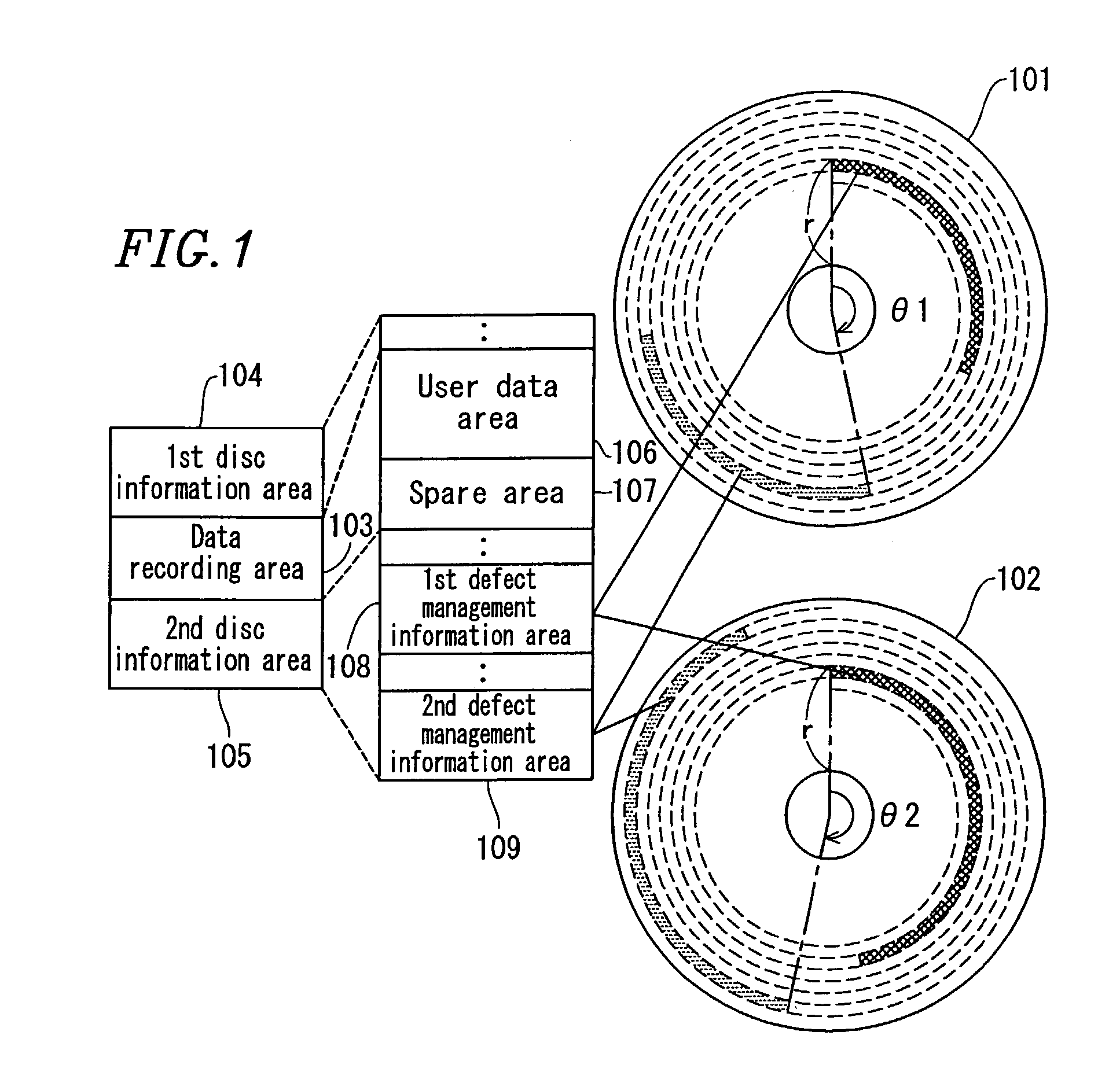
[0050]FIG. 1 shows a logical structure and a schematic view of a first information recording medium 101 and a second information recording medium 102 according to a first example of the present invention.

[0051]The first information recording medium 101 is an exemplary medium usable for a first recording density D1 among a plurality of recording densities. The second information recording medium 102 is an exemplary medium usable for a second recording density D2 among the plurality of recording densities. D1 and D2 are different from each other. The first recording density D1 and the second recording density D2 preferably have such a relationship that an absolute value of the ratio of the difference between the first recording density D1 and the second recording density D2, with respect to the first recording density D1, is 0.05 to 0.1. The first information recording medium 101 and the second information recording medium 102 each have a sector structu...

specific example 1

[0064]Next, the information recording medium according to the first example will be described by way of a specific example.

[0065]The first recording density D1 was 75 mm / block, the second recording density D2 was 80 mm / block, and the radial distance r was 60 mm. In this case, the expressions (1) and (2) mentioned above are as follows:

θ1=(75×N) / (2π×60)×360(Mod360)  (1′)

θ2=(80×N) / (2π×60)×360(Mod360)  (2′)

[0066]θ1 and θ2 were obtained from expressions (1′) and (2′) with the range of N being 1 through 100.

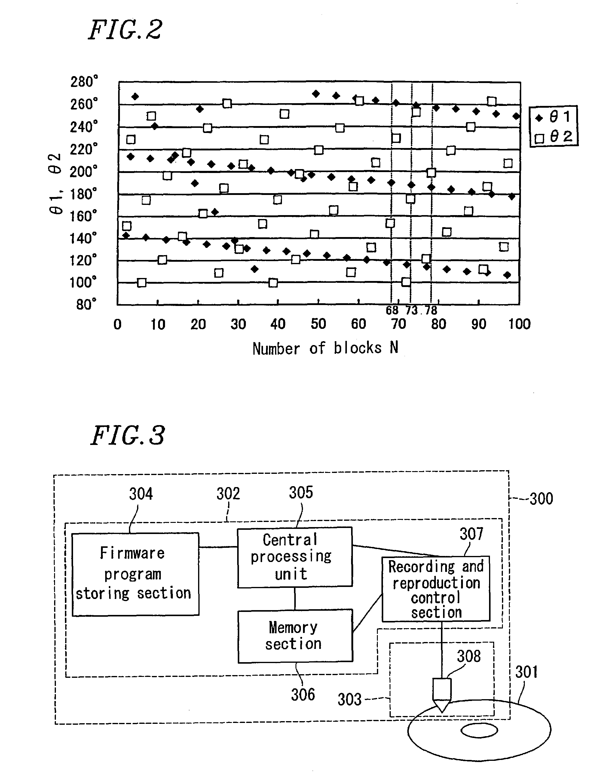
[0067]FIG. 2 is a graph illustrating the relationship between the number of blocks N, and θ1 and θ2 according to the first example. More specifically, FIG. 2 shows θ1 (♦) fulfilling 90°≦θ1≦270° and θ2 (□) fulfilling 90°≦θ2≦270° plotted when N is in the range of 1 through 100. From FIG. 2, it was found that the relationships of 150°≦θ1≦210° and 150°≦θ2≦210° are fulfilled when the number of blocks N is 68, 73 and 78.

[0068]Accordingly, when the number of blocks N existing between the star...

example 2

[0116]In the first example, an information recording medium usable for either the first recording density D1 or the second recording density D2 among a plurality of recording densities has been described. The present invention is not limited to this. In a second example of the present invention, an information recording medium usable for one of three or more recording densities will be described.

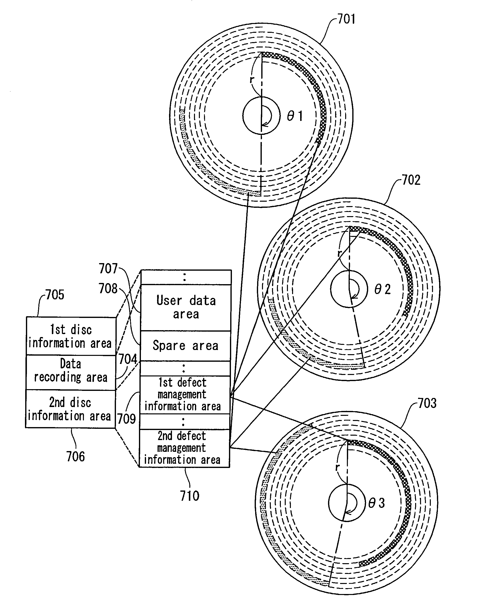
[0117]FIG. 7 shows a logical structure and a schematic view of a first information recording medium 701, a second information recording medium 702, and a third information recording medium 703 according to the second example of the present invention. FIG. 7 shows the recording media usable for three different recording densities for the sake of simplicity.

[0118]The first information recording medium 701 is an exemplary medium usable for a first recording density D1 among three recording densities. The second information recording medium 702 is an exemplary medium usable for a second recordin...


PUM


Abstract

Information recording media 101 and 102 usable for either a first recording density D1 or a second recording density D2 each include a user data area 106 in which user data is to be recorded, a first defect management information area 108 in which first defect management information for managing a defect area in the user data area is to be recorded, and a second defect management information area 109 in which second defect management information having an identical content to that of the first defect management information is to be recorded. The first and second defect management information areas 108 and 109 are located such that angles θ1 and θ2 made by start blocks thereof fulfill the relationships of 150°≦θ1≦210° and 150°≦θ2≦210° (θ1: in the case of the first recording density, and θ2: in the case of the second recording density).

Description

BACKGROUND OF THE INVENTION[0001]1. Field of the Invention[0002]The present invention relates to an information recording medium, a recording apparatus, a reproduction apparatus, a recording method, a reproduction method, and a defect management method providing improved reliability on information.[0003]2. Description of the Related Art[0004]As large capacity information recording media, optical discs such as, for example, DVDs (Digital Versatile Discs) are known. Along with the increase in the amount of information to be recorded on an information recording medium, high density recording technology and large capacity technology have remarkably improved. As such technologies are improved, it is becoming more and more important to guarantee reliability of recorded information.[0005]FIG. 9 shows a logical structure of a conventional information recording medium 900.[0006]The information recording medium 900 includes a data recording area 901, a first disc information area 902, and a s...

Claims


Application Information

Patent Timeline
IPC IPC(8): G11B5/09G11B7/00G11B20/12G11B7/004G11B7/007G11B20/10G11B20/18
CPCG11B20/1217G11B20/1883G11B2220/2537G11B2220/20G11B2020/1893G11B7/007G11B20/10G11B7/0045G11B20/18
Inventor YAMAMOTO, YOSHIKAZUITO, MOTOSHIUEDA, HIROSHI
Owner PANASONIC CORP
Why Eureka
Try Eureka