Reducing delays associated with inserting a checksum into a network message

a network message and checksum technology, applied in data switching networks, multiplex communication, digital transmission, etc., can solve the problems of unsatisfactory network message inserting speed,

Inactive Publication Date: 2006-05-09
ALACRITECH
View PDF97 Cites 155 Cited by
  • Summary
  • Abstract
  • Description
  • Claims
  • Application Information

AI Technical Summary

Benefits of technology

[0008]In this way, the slow write to DRAM of the complete TCP header after the payload has already been transferred to DRAM is avoided. Rather than generating the comple

Problems solved by technology

A difficulty associated with performing this operation quickly is that the checksum of the TCP packet is located near the front of the packet before the data payload.
Unfortunately, the writing to DRAM 105 is

Method used


Image

  • Reducing delays associated with inserting a checksum into a network message
  • Reducing delays associated with inserting a checksum into a network message
  • Reducing delays associated with inserting a checksum into a network message

Examples


Embodiment Construction

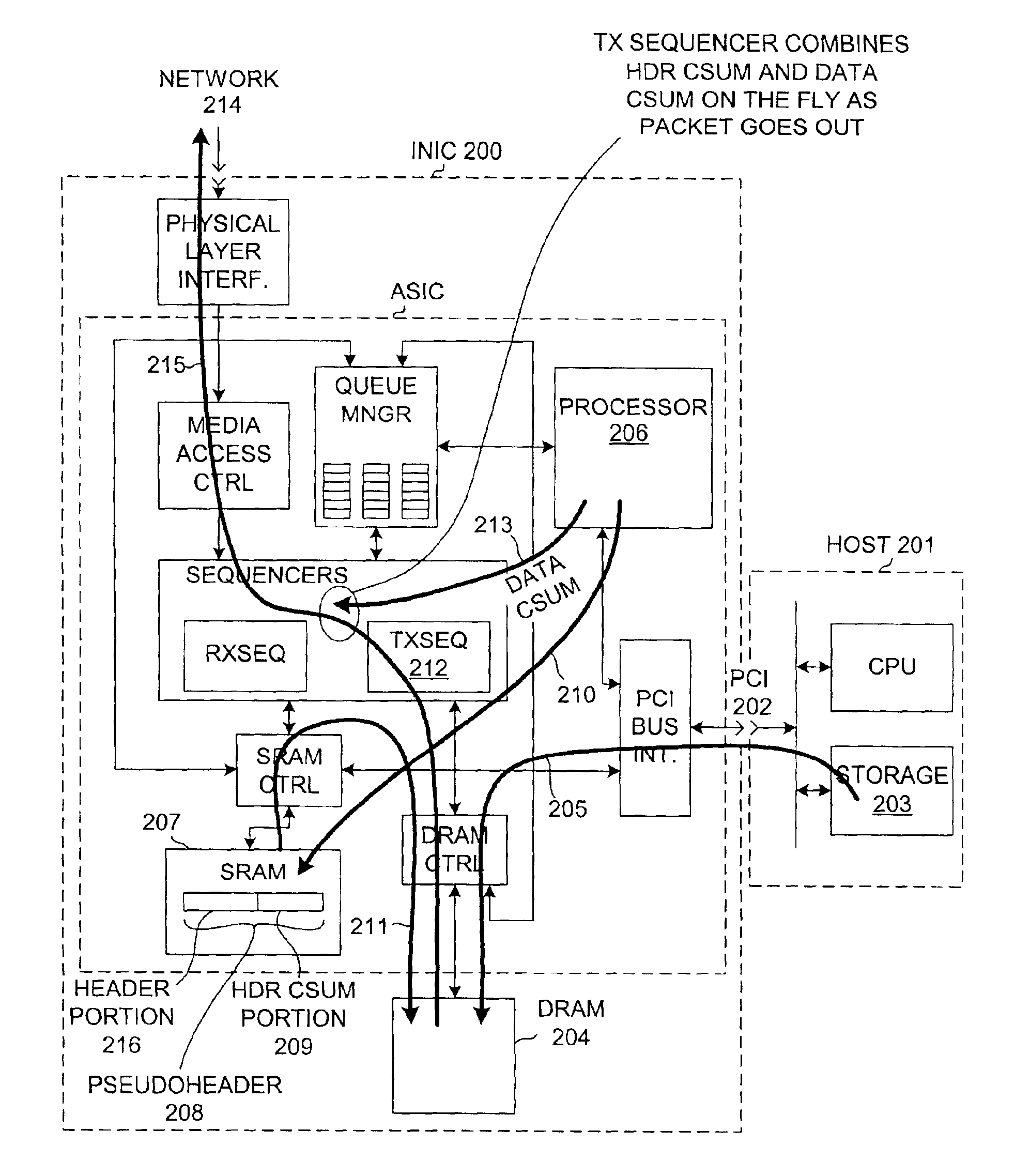
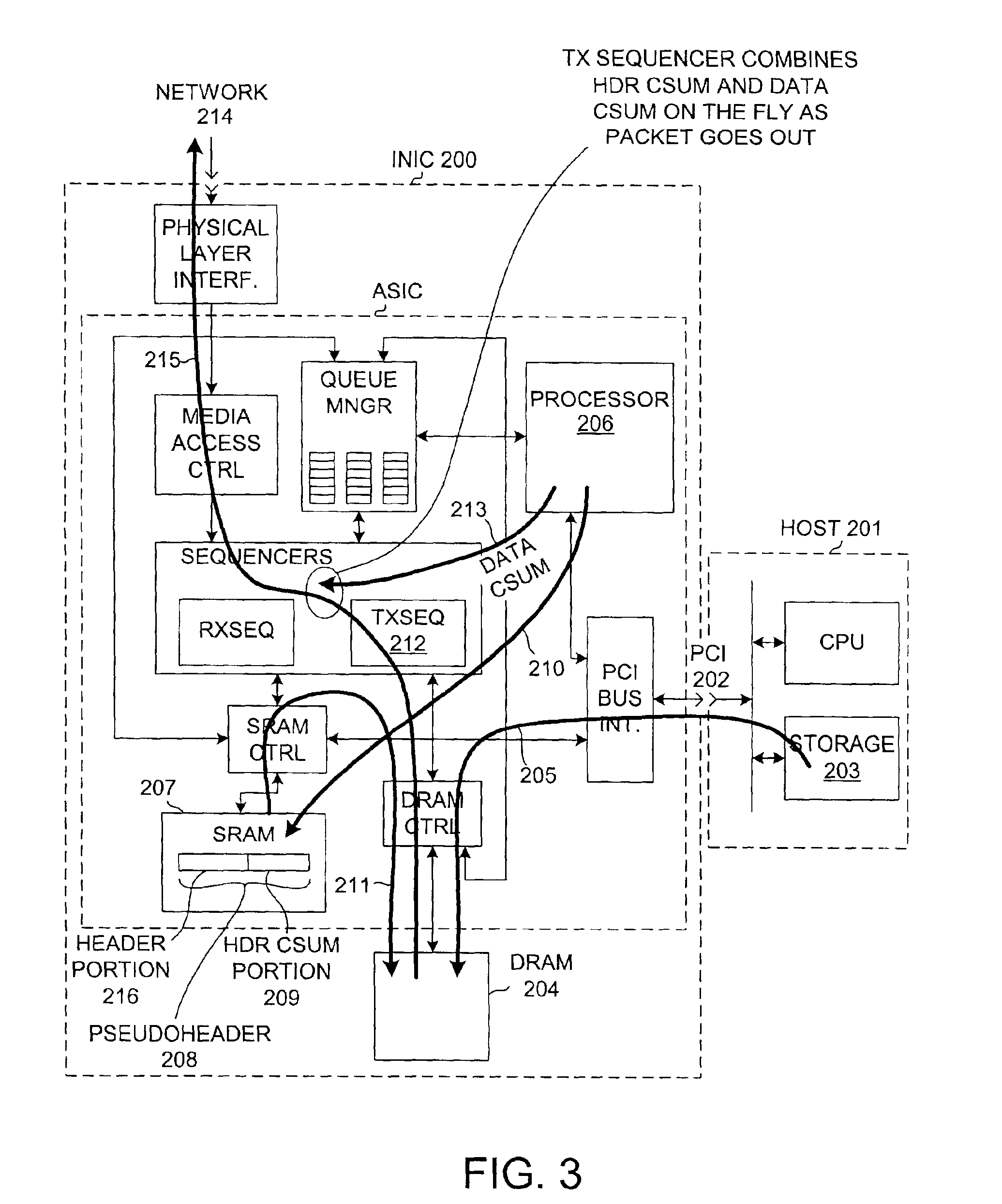
[0014]FIG. 3 is a diagram of an intelligent network interface card (INIC) 200 in accordance with one embodiment of the present invention. INIC 200 is coupled to host computer 201 via PCI bus 202. For additional information on INIC 200, see U.S. patent application Ser. No. 09 / 464,283, filed Dec. 15, 1999 (the subject matter of which is incorporated herein by reference).

[0015]FIG. 4 is a flow chart that illustrates a method in accordance with an embodiment of the invention. In step 300, data from host memory that is to make up a part of the payload of a TCP message is transferred from host memory 203 to DRAM 204 via PCI bus 202. Hardware in the path of this data determines a first checksum CSUM1 on the fly as the data passes by. This flow of data from host memory 203 to DRAM 204 is indicated on FIG. 3 by arrow 205.

[0016]Although it could be in some situations, in the presently described example not all the data that will make up the TCP data payload is present in the same place in hos...


PUM


Abstract

A first partial checksum for the header portion of a TCP header is generated on an intelligent network interface card (INIC) before all the data of the data payload of the TCP message has been transferred to the INIC. A pseudopacket with the first partial checksum and the data is assembled in DRAM on the INIC as the data arrives onto the INIC. When the last portion of the data of the data payload is received onto the INIC, a second partial checksum for the data payload is generated. The pseudopacket is read out of DRAM for transfer to a network. While the pseudopacket is being transferred, the second partial header is combined with the first partial header and the resulting final checksum is inserted into the pseudopacket so that a complete TCP packet with a correct checksum is output from the INIC to the network.

Description

CROSS-REFERENCE TO RELATED APPLICATIONS[0001]This application is a continuation-in-part of and claims the benefit under 35 U.S.C. §120 of U.S. patent application Ser. No. 09 / 464,283, filed Dec. 15, 1999, by Laurence B. Boucher et al., now U.S. Pat. No. 6,427,173, which in turn is a continuation-in-part of and claims the benefit under 35 U.S.C. §120 of U.S. patent application Ser. No. 09 / 439,603, filed Nov. 12, 1999, by Laurence B. Boucher et al., now U.S. Pat No. 6,247,060, which in turn claims the benefit under 35 U.S.C. §119(e)(1) of the Provisional Application Ser. No. 60 / 061,809, filed on Oct. 14, 1997. This application also is a continuation-in-part of and claims the benefit under 35 U.S.C. §120 of U.S. patent application Ser. No. 09 / 384,792, filed Aug. 27, 1999, now U.S. Pat. No. 6,434,620, which in turn claims the benefit under 35 U.S.C. § 119(e)(1) of the Provisional Application Ser. No. 60 / 098,296, filed Aug. 27, 1998. This application also is a continuation-in-part of and ...

Claims


Application Information

Patent Timeline
IPC IPC(8): H04L12/56H04J3/16H04L1/00H04L12/66H04L29/06
CPCH04L1/0061H04L1/0072H04L1/0083H04L47/193H04L49/90H04L49/9042H04L69/12H04L49/9094H04L69/16H04L69/22H04L69/161H04L69/163H04L49/9068
Inventor BLIGHTMAN, STEPHEN E. J.BOUCHER, LAURENCE B.CRAFT, PETER K.HIGGEN, DAVID A.PHILBRICK, CLIVE M.STARR, DARYL D.
Owner ALACRITECH
Why Eureka
Try Eureka