Hinge retarding device such as for vehicle glove compartment lids

Inactive Publication Date: 2006-05-16
ITW FASTEX ITALIA SPA
19 Cites 17 Cited by

AI-Extracted Technical Summary

Problems solved by technology

Retarding devices of both above types have numerous drawbacks: both are expensive and bulky, and neither can be integrated with the hinge structure.
Moreover, friction devices are mechanically complex, not always reliable, and s...

Benefits of technology

[0006]It is an object of the invention to provide a retarding device which is straightforward and inexpensive to produce, extremely compact, may be integrated with a hinge, is reliable, and unaffe...

Abstract

A retarding device insertable between two members connected to rotate relatively about a hinge axis, and which opposes and so retards such rotation in predetermined manner; the device having: a substantially cylindrical support carried integrally by a first of the rotationally connected members and substantially coaxial with the hinge axis; a coil, spring fitted interferentially to the support and terminating with two opposite radial arms projecting towards a second of said members connected to each other for relative rotation; and a retaining seat carried integrally by the second member and on which the arms of the spring rest, on opposite sides, and are stressed by the second member, as a consequence of the aforementioned relative rotation, to deform the spring in such a direction as to progressively reduce and, beyond a certain point of the moving path of the other member, substantially eliminate, the interference with which the spring is fitted to the support. The rotation of the rotationally connected members is broken in a predetermined manner.

Application Domain

Technology Topic

Image

  • Hinge retarding device such as for vehicle glove compartment lids
  • Hinge retarding device such as for vehicle glove compartment lids

Examples

  • Experimental program(1)

Example

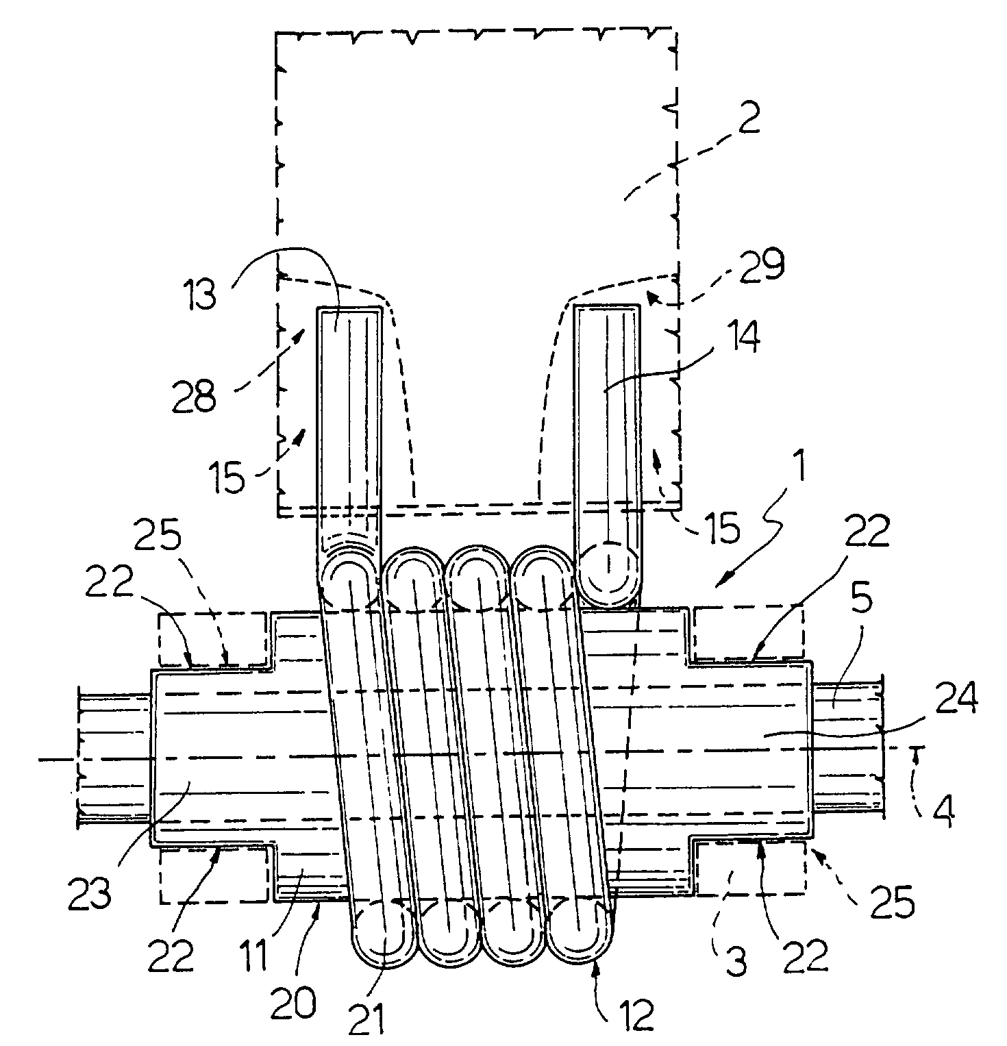
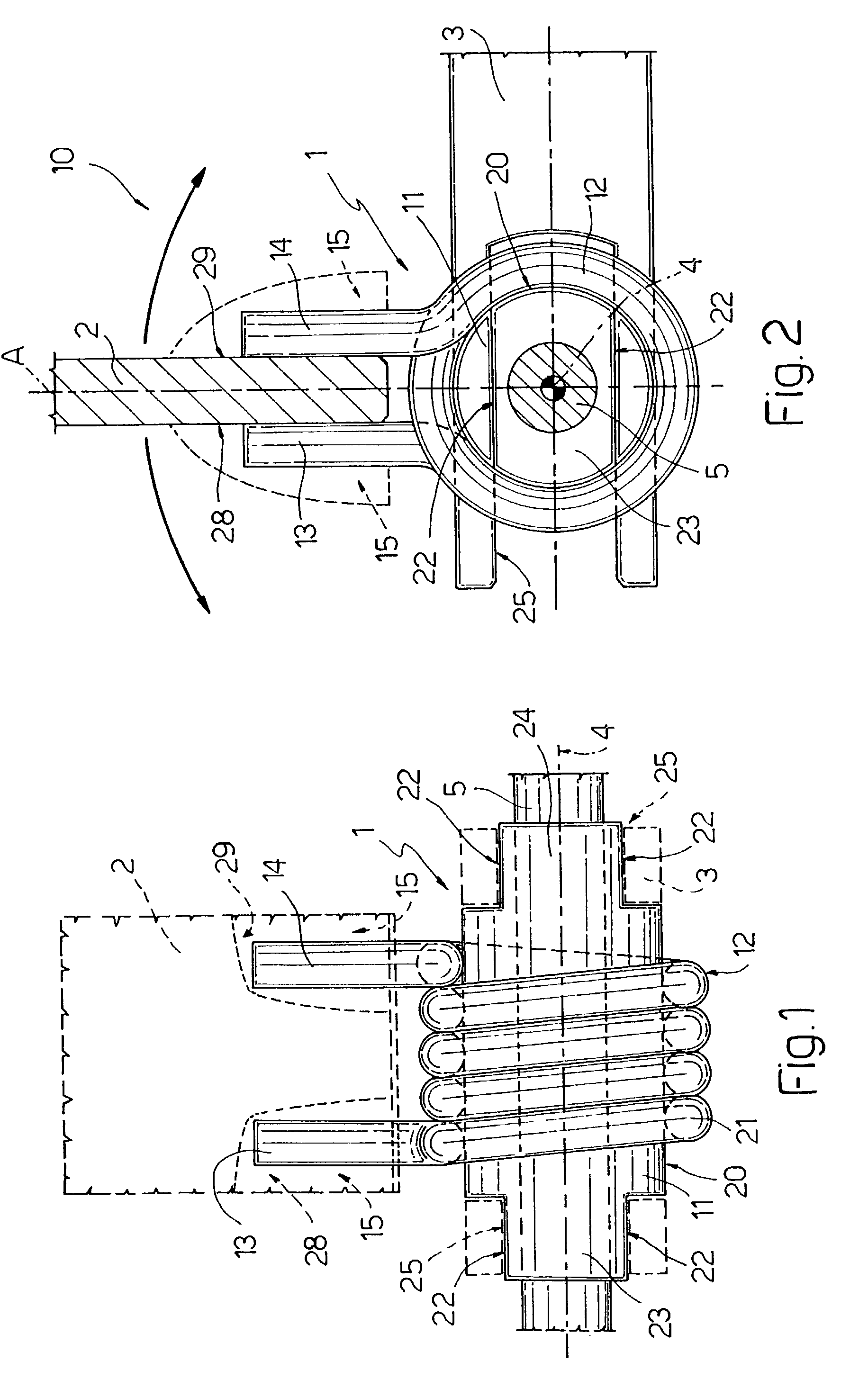
[0017]Retarding device 1 in FIGS. 1 and 2 is insertable between two members 2, 3 connected to rotate relatively about a hinge axis 4, and which, as will be seen, opposes and so retards rotation of the members in a predetermined manner. Members 2, 3 may be any two members movable with respect to each other, e.g., a lid closing an access opening (e.g., to a vehicle glove compartment) and a post defining said opening, or may form part of a hinge device 10 (FIG. 2) hinging the members and integrated with retarding device 1, in which case, members 2, 3 are defined by two half-hinges (e.g., a movable and a fixed half-hinge) connected by a pin 5 to rotate about hinge 15 axis 4.
[0018]According to the invention, device 1 comprises a support 11 carried integrally by one of members 2, 3 (in the example shown, member 3) and is substantially coaxial with hinge axis 4. A coil spring 12 is interference fitted to support 11 and terminates with two opposite radial arms 13, 14 projecting towards the other member (in the example shown, member 2); and at least one retaining seat carried integrally by member 2, and on which arms 13, 14 of spring 12 rest on opposite sides.
[0019]In the non-limiting example shown, member 2 is assumed to be the movable member (rotating about axis 4), and member 3 the fixed member, though the following description also applies conversely. Moreover, though support 11, in the non-limiting example shown, is defined by a substantially cylindrical pin defined by a 5 cylindrical outer lateral surface 20 coaxial with axis 4, it is understood that any support of substantially axial extension and symmetry may perform the same function as cylindrical pin 11.
[0020]According to the invention, spring 12 is interference fitted to cylindrical surface 20 and is made from circular-section music wire of a predetermined diameter, by winding the wire into a coil (defining spring 12) defined by a number of turns and having an inside diameter, when undeformed, smaller than the outside diameter of pin 11 at surface 20.
[0021]According to the invention, pin 11 is fitted integrally and connected angularly to member 3 by prismatic joints defined by circumferential flat surfaces 22 formed on respective opposite ends (e.g., 23) 24 of pin 11, which are fitted inside respective complementary prismatic seats 25 formed integrally in member 3. Pin 11 is preferably molded in one piece from plastic material, or may be made of metal.
[0022]Arms 13 and 14 are defined by respective bent ends of spring 12, which rest laterally—each without crossing the plane of member 2 (indicated A in FIG. 2)—on respective opposite faces 28, 29 of retaining seat/s 15 (FIG. 2). In the simplest embodiment, retaining seat 15 for both arms 13, 14 is defined simply by faces 28, 29, which also define member 2 as a whole. Alternatively, provision may be made for one or more seats 15 (shown schematically by the dash lines) comprising, for example, concavities or appropriate deformations of member 2 and defined partly by faces 28, 29.
[0023]Whichever the case, according to the invention, faces 28, 29 are so formed as to be parallel at all times to the tangents to lateral outer surface 20 of pin 11, so as to rotate relatively about axis 4 in either of the two directions indicated by the arrows in FIG. 2, whenever members 2 and 3 are rotated relatively. As such, in the case of clockwise rotation, face 29 intercepts and rotates arm 14, and face 28 does the same with arm 13 in the case of anticlockwise rotation.
[0024]In the example shown, the two rotationally connected members 2, 3 defining hinge device 10 are connected to each other by pin 5, which is fixed to and angularly integral in known manner with member 2 (as shown by the hatching in the same direction in FIG. 2) and also defines hinge axis 4. Pin 5 is fitted coaxially through pin or support 11, which is therefore tubular, substantially cylindrical, and free to rotate with respect to pin 5, or to remain stationary with member 3 as member 2 rotates. The same result is achieved if pin 5 is also fixed (e.g. forms an integral part of pin 11) and member 2 is connected idly to pin 5 by appropriate seats.
[0025]Whichever the case, by virtue of the structure 5 described, retarding device 1 (and retarded hinge device 10 as a whole) operates as follows.
[0026]Normally, spring 12 is wound tightly about pin 11, thus preventing any rotation between the two.
[0027]When member 2, either acted on manually by the user, by virtue of the thrust exerted by elastic means, or under its own weight, begins rotating about axis 4 in either of the two directions shown by the arrows in FIG. 2, it stresses one of arms 13, 14, which, at rest, rests against opposite faces 28, 29 which, for the reasons described, rotate integrally with member 2. Consequently the arm 13, 14 involved (depending on the rotation direction) is subjected by member 2 to a torque reaction, which is directly proportional to the rotation angle, and which elastically increases the winding diameter of the spiral defined by coil spring 12.
[0028]In other words, the torque transmitted to arms 13, 14, whichever the direction of rotation, tends to elastically deform spring 12 in such a direction as to reduce the interference with which the spring is fitted to support 11, so that the spiral formed by spring 12“opens” to enable spring 12 to rotate with respect to pin 11 and together with member 2. However, the energy required to elastically deform spring 12 sufficiently to enable the spring to rotate dissipates a large part of the energy acting on member2, so that rotation of member 2 is retarded in direct proportion to the initial interference and the elastic twisting force absorbed by the spring (depending on the diameter of wire 21) during deformation.
[0029]The spring 12 opens to such an extent that there is no interfering contact between the spring and the lateral surface 20 of the hinge shaft, allowing the member 2 to rotate freely about hinge axis 4. In this manner, the member 2 is able to move into contact against the stationary member 3 by quickly completing the closing path of the member 2, e.g., completing the closing path of the door of a glove compartment.
[0030]During the motion of the member 2 caused by force, e.g., externally applied or spring-loaded, the force applied to spring 12 is caused by the force applied, i.e., transmitted through the arms 13, 14, but also by gravity acting on the member 2 which is also transmitted through arms 13, 14. Depending on the angular position of the moving member 2, a similar weight member 2 may exert a different torque depending on its angular position. That is, if the member 2 is vertically oriented with respect to hinge axis 4, the center of gravity passes substantially through the hinge and substantially no torque is applied. If the member is horizontal with respect to hinge axis 4, the center of gravity passes at the maximum distance from the hinge axis and the maximum torque is exerted by the weight of the cover on the spring 12.
[0031]The same principle, according to, a variation not shown, could also be applied in reverse, e.g., by housing a coil spring interferentially inside a cylindrical seat from which the arms project, and by connecting the arms to the movable member so that, during relative rotation, the arms subject the spring to such a torque as to elastically close (i.e., reduce the diameter of) the spiral. Clearly, however, the preferred embodiment described is much easier to assemble.

PUM

no PUM

Description & Claims & Application Information

We can also present the details of the Description, Claims and Application information to help users get a comprehensive understanding of the technical details of the patent, such as background art, summary of invention, brief description of drawings, description of embodiments, and other original content. On the other hand, users can also determine the specific scope of protection of the technology through the list of claims; as well as understand the changes in the life cycle of the technology with the presentation of the patent timeline. Login to view more.

Similar technology patents

Compact folding seat

ActiveUS20050264065A1Extremely compactEasy to operateKids chairsChild seatsMechanical engineering
Owner:DIONO

Oscillator based on series of four nanowires

ActiveUS20100219897A1Extremely compactEasy to implementPulse generation by logic circuitsOscillations generatorsPhysicsResonator
Owner:COMMISSARIAT A LENERGIE ATOMIQUE ET AUX ENERGIES ALTERNATIVES

Proteosome influenza vaccine

InactiveUS7399840B2Straightforward to produceSsRNA viruses negative-senseAerosol deliveryProteasomeInfluenza vaccine
Owner:ID BIOMEDICAL CORP LAVAL

Classification and recommendation of technical efficacy words

  • Straightforward to produce
  • Extremely compact

Proteosome influenza vaccine

InactiveUS7399840B2Straightforward to produceSsRNA viruses negative-senseAerosol deliveryProteasomeInfluenza vaccine
Owner:ID BIOMEDICAL CORP LAVAL

Compact folding seat

ActiveUS20050264065A1Extremely compactEasy to operateKids chairsChild seatsMechanical engineering
Owner:DIONO

Oscillator based on series of four nanowires

ActiveUS20100219897A1Extremely compactEasy to implementPulse generation by logic circuitsOscillations generatorsPhysicsResonator
Owner:COMMISSARIAT A LENERGIE ATOMIQUE ET AUX ENERGIES ALTERNATIVES
Why Eureka
Try Eureka