Measuring instrument

a technology of measuring instruments and measuring cylinders, applied in the field of measuring instruments, can solve the problems of increasing the machining cost and the problem of its operational performance, and achieve the effect of enhancing the measurement accuracy of the measuring instrumen

Active Publication Date: 2006-05-16
MITUTOYO CORP
View PDF15 Cites 1139 Cited by
  • Summary
  • Abstract
  • Description
  • Claims
  • Application Information

AI Technical Summary

Benefits of technology

[0009]With such a configuration, when the spindle is rotated, the spindle is advanced and retracted along with screwing rotation of the spindle against the main body. Counting a rotation amount of the spindle at this time, the displacement of the spindle can be figured out according to the movement pitch per rotation of the spindle, thus obtaining the measurement value.
[0025]With this arrangement, since the V-shaped groove is widened toward the upper side and narrowed toward the lower side, the tip end of the engaging pin is abutted on the both sides of the V-shaped engaging groove without clearance. Besides, the tip end of the engaging pin is spherical, the contacting surface between the engaging pin and the engaging groove defines a point, the frictional force of which is small. Therefore, the engaging pin can slide on the engaging groove, as well as the engaging pin can fit to the engaging groove without clearance. Consequently, the measurement accuracy of the measuring instrument can be enhanced.

Problems solved by technology

However, since the screw pitch of the male screw formed on the spindle is 0.5 mm or 0.635 mm, the spindle must be rotated for many times as an object to be measured is changed because the displacement per rotation of the spindle is small, thus raising a problem on its operational performance.
In the case of the triple thread screw, although three outside helixes for a screw need to be formed with the phase difference by 120 degrees, it is difficult to machine such a multiple thread screw with that phase difference maintained precisely, and machining error may cause measurement error.
Additionally, it is also difficult to accurately form many outside helixes with the equal pitch, thereby increasing the machining cost thereof as the number of the outside helixes increasing.

Method used


Image

  • Measuring instrument
  • Measuring instrument
  • Measuring instrument

Examples


Embodiment Construction

[0037]An embodiment of the present invention will be described below with reference to the attached drawings.

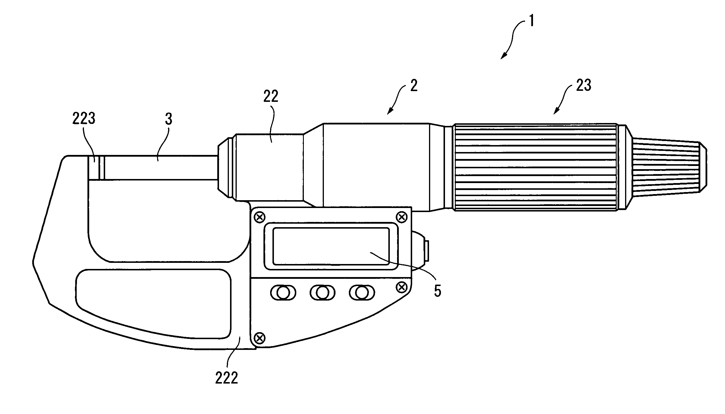
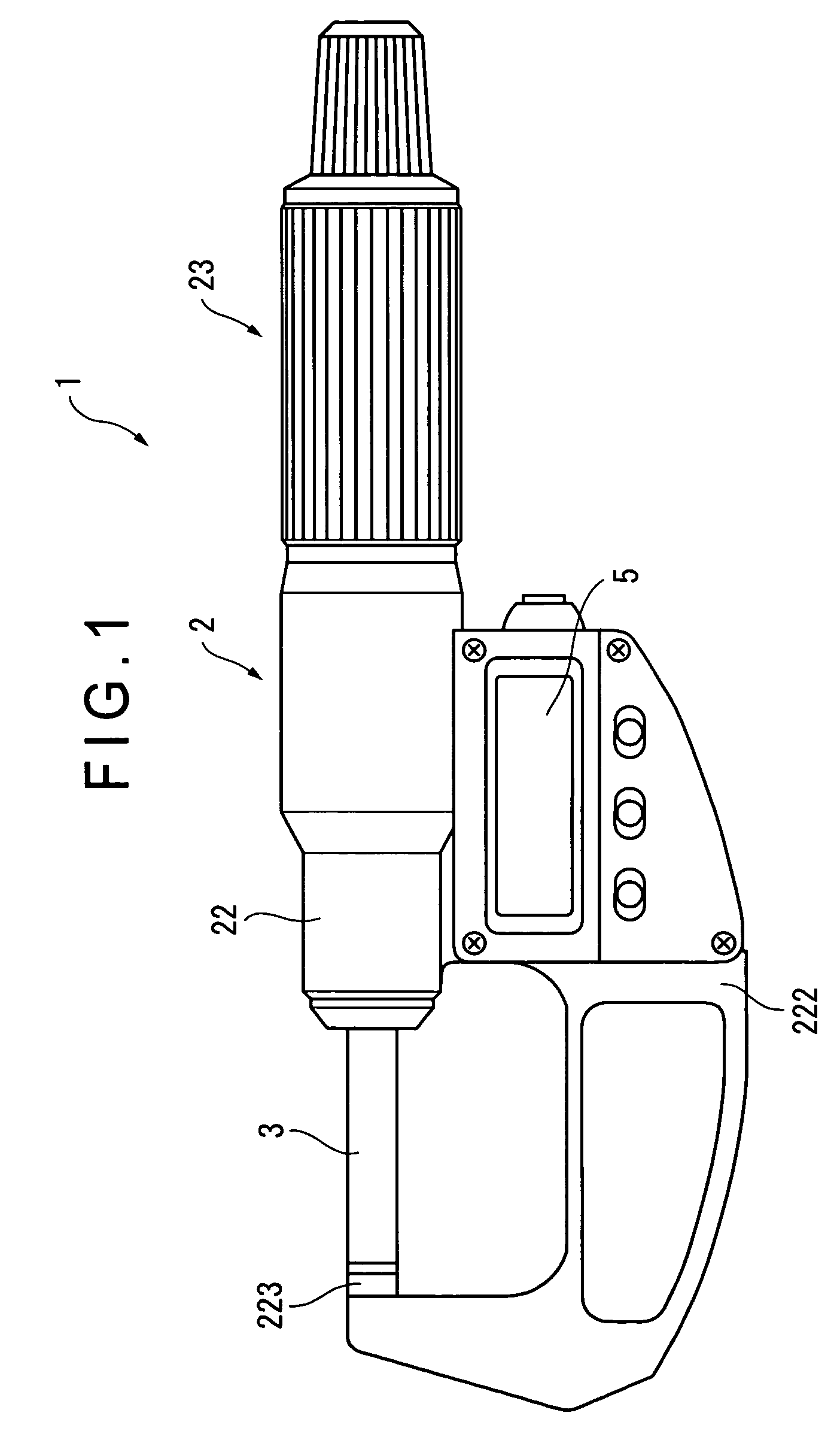
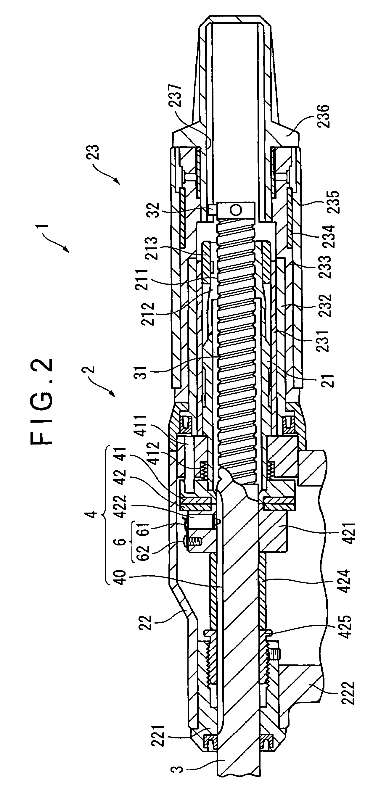
[0038]FIG. 1 shows a micrometer, which is a first embodiment of a measuring instrument according to the present invention. FIG. 2 shows a cross-sectional view of FIG. 1.

[0039]This micrometer 1 includes a main body 2 having an anvil 223 at an end of a substantially U-shaped frame 222, a spindle 3 being screwed at the other end of the main body 2 and being advanced to and retracted from the anvil 223 in an axial direction along with its screwing rotation, a detector 4 that detects displacement of the spindle 3 in the axial direction from a rotation amount of the spindle 3, and a digital display 5 which is a display unit for displaying a measurement value on the basis of a detection signal from the detector 4.

[0040]The main body 2 includes a front tube 22, a rear tube 21 and a spindle rotating portion 23 sequentially arranged from an end of the main body 2.

[0041]The front tube 2...


PUM


Abstract

A measuring instrument that includes a tube 21 having a female thread 211 and a spindle 3 having a lead screw 31 screwing with the female thread 211 and capable of being advanced and retracted in an axial direction along with rotation around the axial center, and measures dimensions etc. of a workpiece according to displacement in an axial direction of the spindle 3 based on a rotation amount of the spindle 3. According to this measuring instrument, a pitch P of the lead screw 31 is twice as large or more than the difference between an external diameter R and a core diameter r thereof, and the difference between the external diameter R and the core diameter r is one-fifth or less of the external diameter R. Because of the lead screw 31 with the large pitch, the spindle 3 can be moved at high speed, thus enhancing operational performance of the measuring instrument.

Description

TECHNICAL FIELD[0001]The present invention relates to a measuring instrument that measures dimensions etc. of a workpiece by advancing and retracting a spindle along with its screwing rotation, for instance, the present invention relates to a measuring instrument as typified by a micrometer or a micrometer head.BACKGROUND ART[0002]Conventionally, there has been known a measuring instrument, for instance, the one typified by a micrometer, a micrometer head or the like, that has a main body provided with a female thread and a spindle provided with a male screw, and measures dimensions etc. of a workpiece by advancing and retracting the spindle along with its screwing rotation. An example of the measuring instrument is disclosed in, for instance, Reference 1: JP S49-80260U, Reference 2: JP S54-130152A.[0003]According to such a measuring instrument, displacement per rotation of the spindle is defined by a screw pitch of the male screw formed on the spindle.[0004]The screw pitch of the m...

Claims


Application Information

Patent Timeline
Patent Type & Authority Patents(United States)
IPC IPC(8): G01B3/18
CPCG01B3/18
Inventor HAYASHIDA, SHUUJIFUJIKAWA, YUJIICHIKAWA, YUICHISAITO, OSAMUHAYASHI, NOBUYUKINAKAMURA, TAKAHIROHASHIMOTO, YUUZOUOMORI, TOMIO
Owner MITUTOYO CORP
Why Eureka
Try Eureka