Control method for an exhaust gas purification system and an exhaust gas purification system

a technology of exhaust gas purification system and control method, which is applied in the direction of electrical control, machines/engines, separation processes, etc., can solve the problems of clogging of the filter, inability to re-generate the filter, and increase the frequency of manual regeneration caused by switching operation, so as to increase the ease of operation for drivers and reduce the effect of manual regeneration frequency

Inactive Publication Date: 2006-05-16
ISUZU MOTORS LTD
View PDF15 Cites 44 Cited by
  • Summary
  • Abstract
  • Description
  • Claims
  • Application Information

AI Technical Summary

Benefits of technology

[0021]The object of the present invention is to provide a control method of exhaust gas purification system and the exhaust gas purification system which are capable of reducing remarkably the frequency of forced regeneration by the operation of a manual regeneration switch and improving the operability for the driver, in an exhaust gas purification system for prompting the driver to stop the vehicle and execute the forced regeneration by operating a manual regeneration switch through a warning such as flashing of an indicator, in the case of detecting that the detected collecting quantity is higher than a predetermined judgment collecting quantity, concerning the regeneration of a continuous regeneration-type DPF device.
[0034]According to the aforementioned composition, PM is incinerated for some degree through acceleration of PM burning, namely, regeneration of a DPF, by performing a multi-injection whose injection quantity is lower than that of the post-injection and raising the exhaust gas temperature little by little, in the case where the collecting quantity exceeds a threshold of a first temperature rising judgment collecting quantity, by setting this threshold before a predetermined judgment collecting quantity where the PM collecting quantity to the DPF alerts the manual regeneration request, namely, flashes an indicator for prompting to press a manual regeneration switch, for the purpose of allowing users having many traveling patterns that will increase the frequency of forced regeneration by the operation of the manual regeneration switch to drive the vehicle to such a travel distance that evaporates oil dilution and enables the forced regeneration during the traveling. Besides, the multi-injection is stopped when the collecting quantity lowers to a predetermined level, because the fuel consumption deteriorates, if the multi-injection is sustained in this state. It should be appreciated that this exhaust gas temperature raising control by multi-injection accelerates PM removal, being executed also during the vehicle stopping.
[0035]And, this exhaust gas temperature raising control by multi-injection is executed to the extent that the travel distance does not provoke problems by oil dilution in the case of performing the manual forced regeneration and, at the same time, within a range not to perform the forced regeneration automatically.
[0038]Consequently, the frequency of the manual regeneration required when the collecting quantity of collected matters reaches the predetermined judgment collecting quantity, can be reduced. For this reason, the frequency of the manual regeneration caused by switching operation can be drastically reduced and the driver's ease of operation can be increased.

Problems solved by technology

Howsoever, these continuous regeneration-type DPF devices also cause the problem of exhaust pressure rise by the clogging of this filter.
However, in the case of low exhaust gas temperature and in an operating condition of an internal combustion engine where the emission of NO is low, for example, in the case where the low exhaust gas temperature state such as idling operation of internal combustion engine, low load / low speed operation continues, the oxidation reaction is not stimulated as the exhaust gas temperature is low, the catalyst temperature lowers and the catalyst is not activated and, moreover, NO lacks.
Consequently, the aforementioned reaction does not occur and the filter can not be regenerated through oxidation of PM.
As a result, PM continues to be accumulated in the filter and the filter clogging progresses.
However, if the forced regeneration processing is executed during the traveling of a vehicle, as the engine speed is higher than that of the idling regeneration, the post-injection quantity increases necessarily, making the post-injection control during the transition phase difficult.
In short, it is difficult to avoid useless injections (useless shot) such as persistent post-injection when the load changes and the engine temperature rises in the transition state, or deceleration before the exhaust gas temperature rises even if the post-injection is executed.
On the other hand, it has been found that it is not the case for the forced regeneration control in the idling in the vehicle stop state, and oil dilution is relatively few.
Consequently, there is a problem that PM (collected matter) does not accumulate at the center of the filter (DPF), but is biased to accumulate outside circumferentially, causing its clogging.
This enlargement causes fusion damage due to the thermal runaway producing a high temperature state in the filter.
However, if this method is adopted, manual regeneration will be required often, in the case of a vehicle or the like having many patterns of traveling in a low speed, high load operation state.
As a result, there is a problem that the driver will feel it troublesome.

Method used


Image

  • Control method for an exhaust gas purification system and an exhaust gas purification system
  • Control method for an exhaust gas purification system and an exhaust gas purification system
  • Control method for an exhaust gas purification system and an exhaust gas purification system

Examples


Embodiment Construction

[0045]Hereinafter, the preferred embodiments of the control method for an exhaust gas purification system and the exhaust gas purification system according to the present invention will be described with reference to the accompanying drawings. The following explanation will use the example of an exhaust gas purification system provided with a continuous regeneration-type diesel particulate filter (DPF) device comprising a combination of an oxidation catalyst and a filter with catalyst.

[0046][Configuration of Exhaust Gas Purifying System]

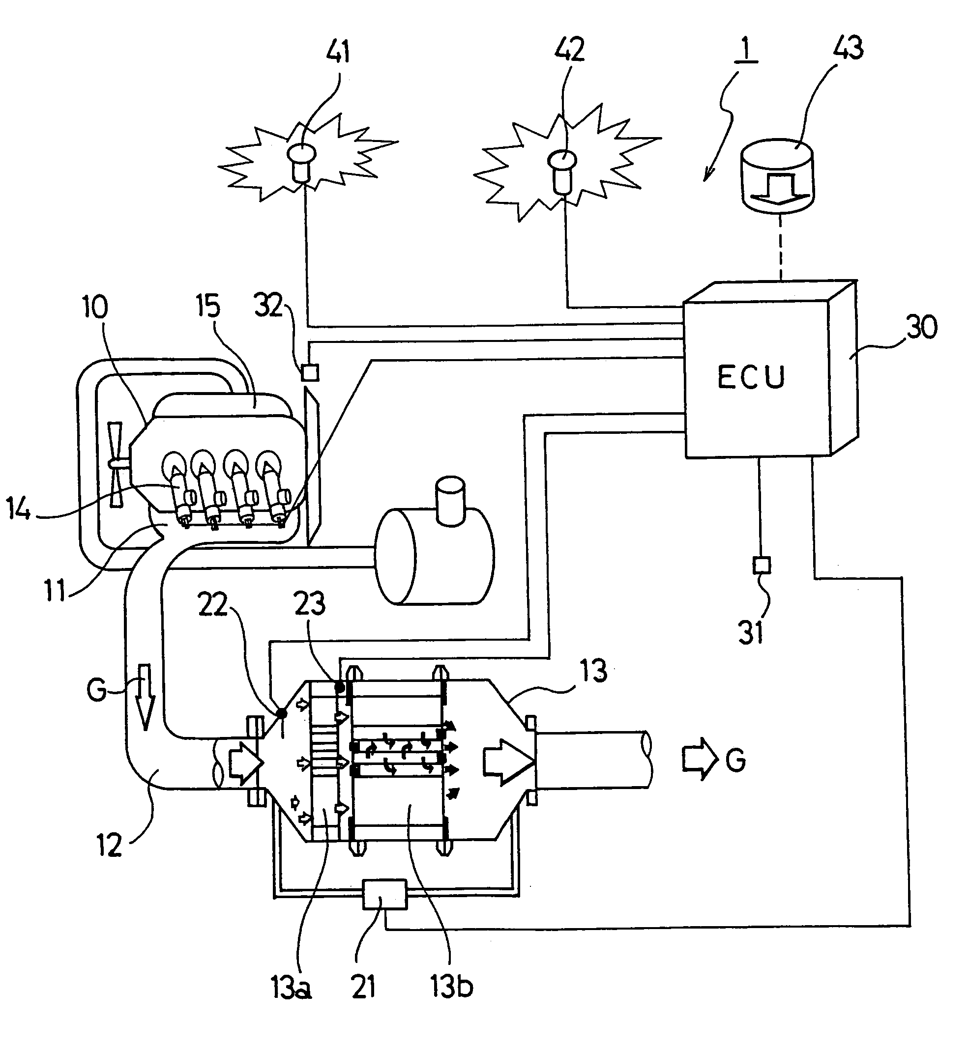
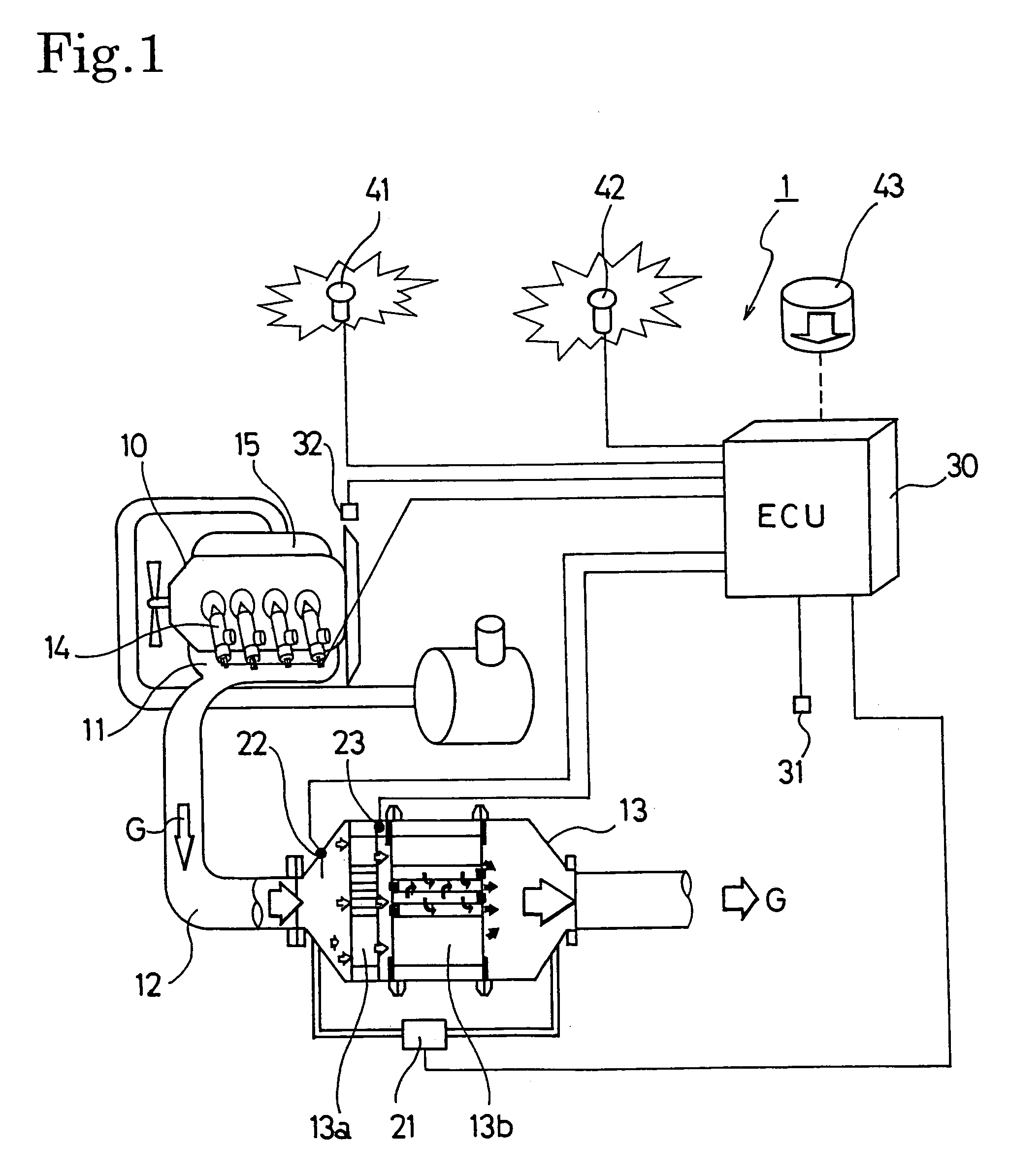
[0047]FIG. 1 shows the configuration of an exhaust gas purification system 1 for an internal combustion engine according to an embodiment of the present invention. This exhaust gas purification system 1 is configured to provide a continuous regeneration-type DPF 13 on an exhaust passage 12 connected to an exhaust manifold 11 of a diesel engine 10. This continuous regeneration-type DPF 13 is configured with an oxidation catalyst 13a on the upstream si...


PUM

PropertyMeasurementUnit
temperatureaaaaaaaaaa

Abstract

An exhaust gas purification system (1) including a continuous regeneration-type DPF (13) and a DPF control (30c) is composed to perform an exhaust gas temperature raising control by multi-injection in the case where the collecting quantity (ΔPm) exceeds a first temperature rising judgment collecting quantity (ΔP01) lower than a predetermined collecting quantity (ΔP1) and, thereafter, to stop the exhaust gas temperature raising control by multi-injection in the case where the collecting quantity (ΔPm) becomes lower than a predetermined second temperature rising judgment collecting quantity (ΔP02) lower than the predetermined first temperature rising judgment collecting quantity (ΔP01).Thereby, frequency of the manual regeneration switch operation can be reduced remarkably, and the operability for a driver can be improved, in the exhaust gas purification system (1) prompting the driver to stop the vehicle and perform the forced regeneration by the manual regeneration switch, in the case of detecting that the detected collecting quantity (ΔPm) is higher than the predetermined judgment collecting quantity (ΔP1), concerning the regeneration of the continuous regeneration-type diesel particulate filter device (13).

Description

BACKGROUND OF THE INVENTION[0001]The present invention relates to an exhaust gas purification system that purifies particulate matters (PM) from the exhaust gas discharged by diesel and other internal combustion engines using a continuous regeneration-type diesel particulate filter (DPF) and also to a control method thereof.[0002]In the same way as for NOx, CO, and also HC etc., restrictions on the volume of particulate matters (hereinafter “PM”) discharged from internal combustion engines such as diesel engines grow severe every year. Techniques for collecting this PM in a filter known as a diesel particulate filter (hereinafter “DPF”) and for reducing the quantity thereof by discharging externally have been developed.[0003]DPFs for collecting this PM include a monolithic honeycomb form wall flow type filter made of ceramic, a fiber form type filter made of fiber shape ceramic or metal, and so on. An exhaust gas purification system using these DPFs is installed on the way of the ex...

Claims


Application Information

Patent Timeline
Patent Type & Authority Patents(United States)
IPC IPC(8): F01N3/00F02D45/00B01D46/42B01D53/94F01N3/02F01N3/023F01N3/24F02D41/02F02D41/38F02D41/40
CPCF01N3/0231F02D41/029F02D41/402Y02T10/44F02D2041/228F02D2200/0812F02D2250/11F02D41/405F02D41/0245F02D41/025F02D2200/604Y02T10/12Y02T10/40
Inventor ONODERA, TAKAOMASHIKO, TATSUO
Owner ISUZU MOTORS LTD
Why Eureka
Try Eureka