Leading and trailing edge stitch tab scrap strippers

a stitch tab and stripper technology, applied in the field of stitch tab scrap strippers, can solve the problems of not being able to properly eject the scraps, not being able to ship or transport fully set up or erected empty paperboard boxes, and cutting the scraps from box blanks

Active Publication Date: 2006-05-16
BENTON IND
View PDF12 Cites 19 Cited by
  • Summary
  • Abstract
  • Description
  • Claims
  • Application Information

AI Technical Summary

Benefits of technology

[0018]Still a further object of the present invention is to provide leading and trailing edge stitch tab scrap strippers which do not require modification of the upper male slotter head and the cooperating lower die cutting anvil.
[0019]Even yet another object of the present invention is to provide stitch tab scrap strippers which operate in a predictable, repeatable manner to insure that each stitch tab scrap is stripped.

Problems solved by technology

Clearly, it is not efficient to ship or transport fully set up or erected empty paperboard boxes from the box manufacturer to a product manufacturer, who will then fill these erected corrugated paperboard cartons with his product.
Specifically, the stitch tab scraps that have been cut from the box blanks, by operation of the stitch tab die cutting blocks and the cooperating lower die cutting anvil, are not ejected properly.
This frequently occurs because the transverse stitch tab cutting knife is not properly located and does not cut across the stitch tab all the way to the stitch tab slot.
The depth of cut of the cutting knife may be set incorrectly or the cutting knife may shift during production.
The resilient surface of the lower die cutting anvil may be irregular due to prolonged usage and may not cooperate with the knife of the cutting die to define a proper cutting point.
Whatever the cause, the result is that the stitch tab scrap is not cleanly severed from the leading and / or trailing edge of the box blank.
The inclusion of these non-stripped or non-ejected stitch tab scraps in the otherwise finished product prepared by the box blank manufacturer is not acceptable.
It results in a product that cannot be properly stacked and handled by automatic machines.
It also results in a product that is not truly finished.
In use, these prior art stitch tab stripping devices have not met with a great deal of commercial success.
They are often too complicated, require modifications to the die cutting blocks, do not function properly and simply do not perform in a dependable, repeatable manner to separate the stitch tab scraps from the blanks.

Method used


Image

  • Leading and trailing edge stitch tab scrap strippers
  • Leading and trailing edge stitch tab scrap strippers
  • Leading and trailing edge stitch tab scrap strippers

Examples


Embodiment Construction

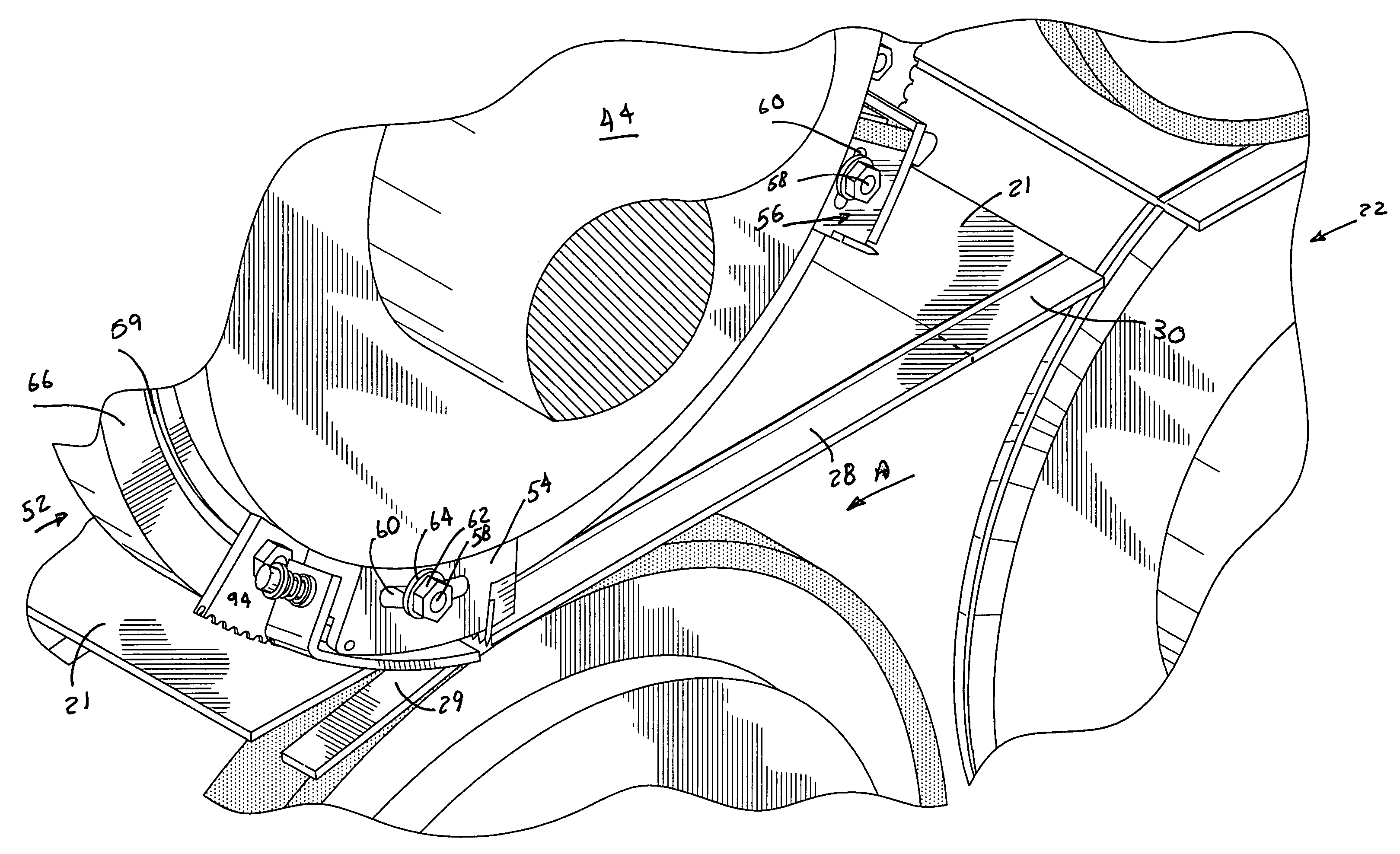
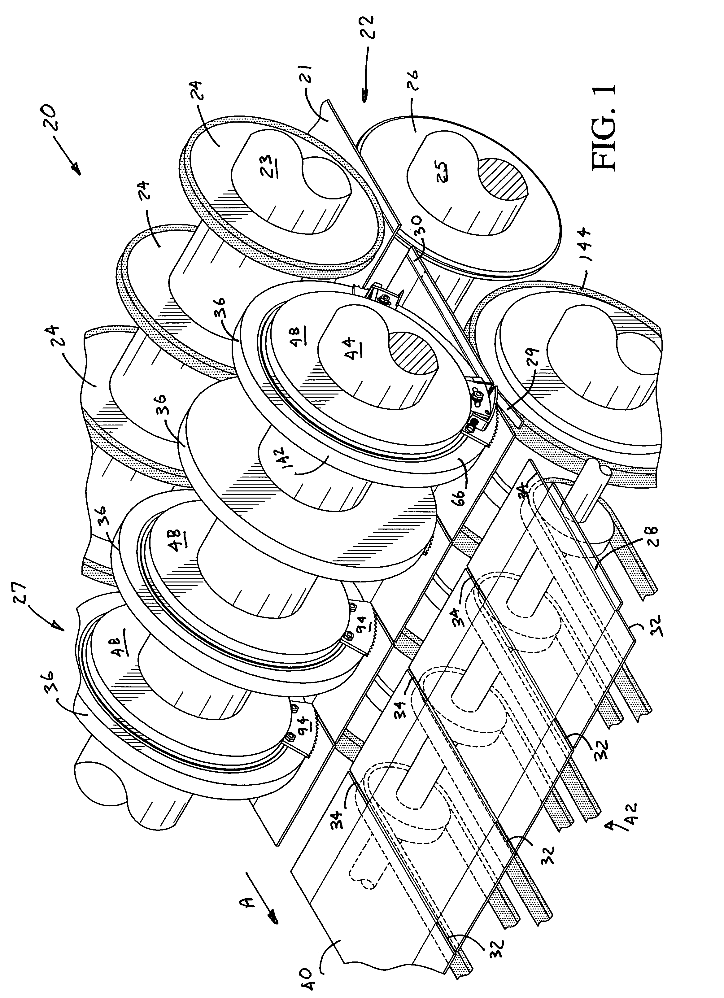
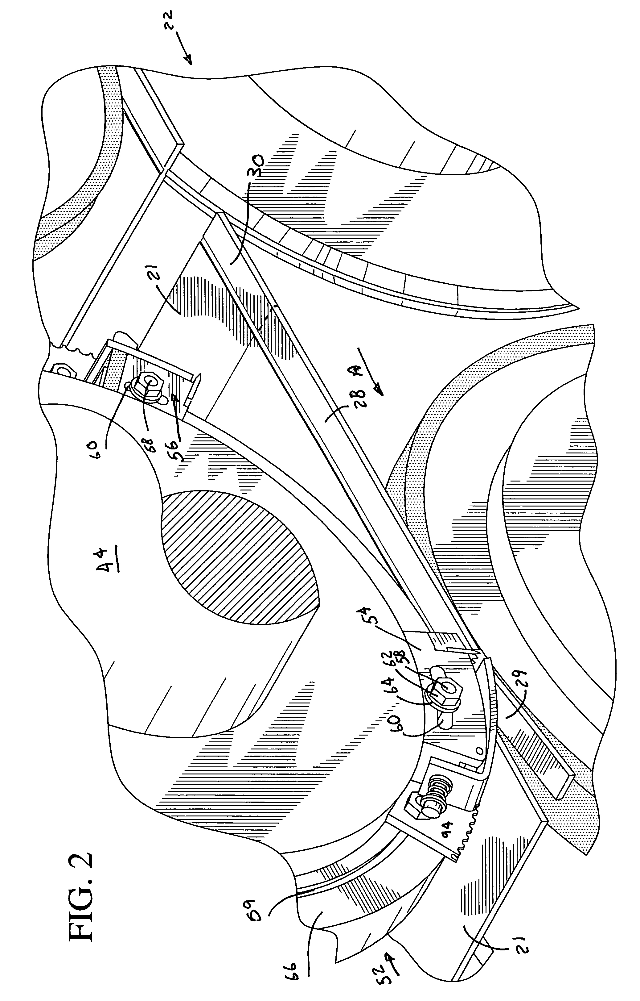
[0041]Referring initially to FIG. 1, there may be seen, generally at 20, a first preferred embodiment of a leading and trailing edge stitch tab scrap stripper apparatus in accordance with the present invention. The leading and trailing edge stitch tab scrap stripper apparatus 20 is part of a much larger corrugated printer-slotter, which is not specifically depicted since it does not, itself, form a part of the present invention. Such an overall corrugated paperboard box blank printer-slotter, and its associated sheet delivery and stacking arrangements are fully described and depicted in applicant's co-pending U.S. patent application Ser. No. 10 / 253,696 which was filed on Sep. 25, 2002 and the entire specification and drawings of which are expressly incorporated herein by reference.

[0042]As may be seen in FIG. 1, a corrugated paperboard box blank 21, which may have been printed, is received from the printing cylinder of the printer-slotter, which is not specifically shown, by a set o...


PUM

PropertyMeasurementUnit
resilientaaaaaaaaaa
biasing forceaaaaaaaaaa
forceaaaaaaaaaa

Abstract

Leading and trailing edge stitch tab scrap strippers utilize pivot arms which are secured to die block bodies for pivotable motion intermediate their two ends. One end of each arm is adapted to engage a stitch tab scrap portion to be stripped and to effect the removal of the tab scrap from a box blank from which it has been cut. A biasing force is applied against a second end of the pivot arm. The pivot arm is caused to pivot in response to the rotation of an upper male slotting head and a lower die cutting anvil. This pivotal movement is effective to strip or to eject the severed stitch tab scrap.

Description

CROSS-REFERENCE TO RELATED APPLICATIONS[0001]The subject U.S. patent application claims priority to U.S. provisional patent application No. 60 / 457,590, filed Mar. 27, 2003. The specification of that provisional patent application is incorporated herein by reference.FIELD OF THE INVENTION[0002]The present invention is directed generally to a stitch tab scrap stripper. More particularly, the present invention is directed to leading and trailing edge stitch tab scrap strippers. Most specifically, the present invention is directed to leading and trailing edge stitch tab scrap strippers for use with a corrugated paperboard box blank machine. During a stitch tab cutting process, scraps of corrugated paper are cut from the leading and trailing edges of corrugated paperboard box blanks. These stitch tab scraps must be separated from the box blanks before the box blanks are further processed. The leading and trailing edge stitch tab scrap strippers, in accordance with the present invention, ...

Claims


Application Information

Patent Timeline
Patent Type & Authority Patents(United States)
IPC IPC(8): B26D7/18
CPCB26D7/1818B26D3/14Y10T83/2105Y10T83/2109Y10T83/2113
Inventor SMITH, RICHARD W.
Owner BENTON IND
Why Eureka
Try Eureka