
Fuel injectors

a technology of fuel injectors and injectors, which is applied in the direction of fuel injection apparatus, charge feed system, spraying apparatus, etc., can solve the problems of typical noise, and achieve the effect of preventing noise leakag

Inactive Publication Date: 2006-05-16
AISAN IND CO LTD
View PDF7 Cites 4 Cited by
  • Summary
  • Abstract
  • Description
  • Claims
  • Application Information

AI Technical Summary

Benefits of technology

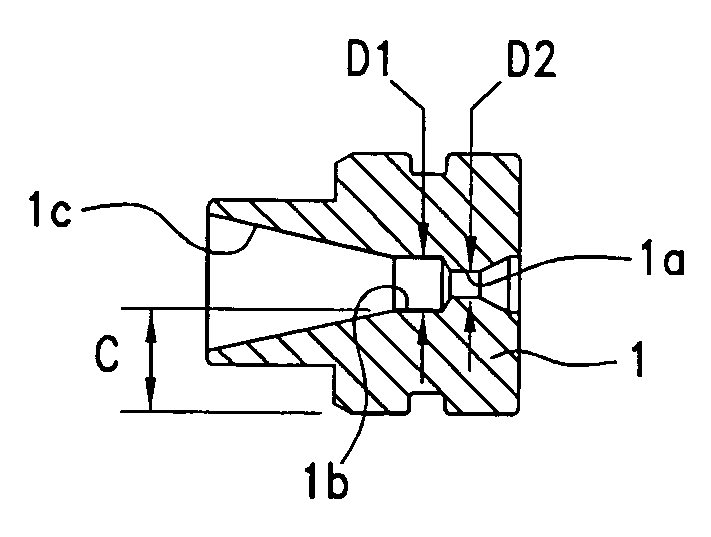
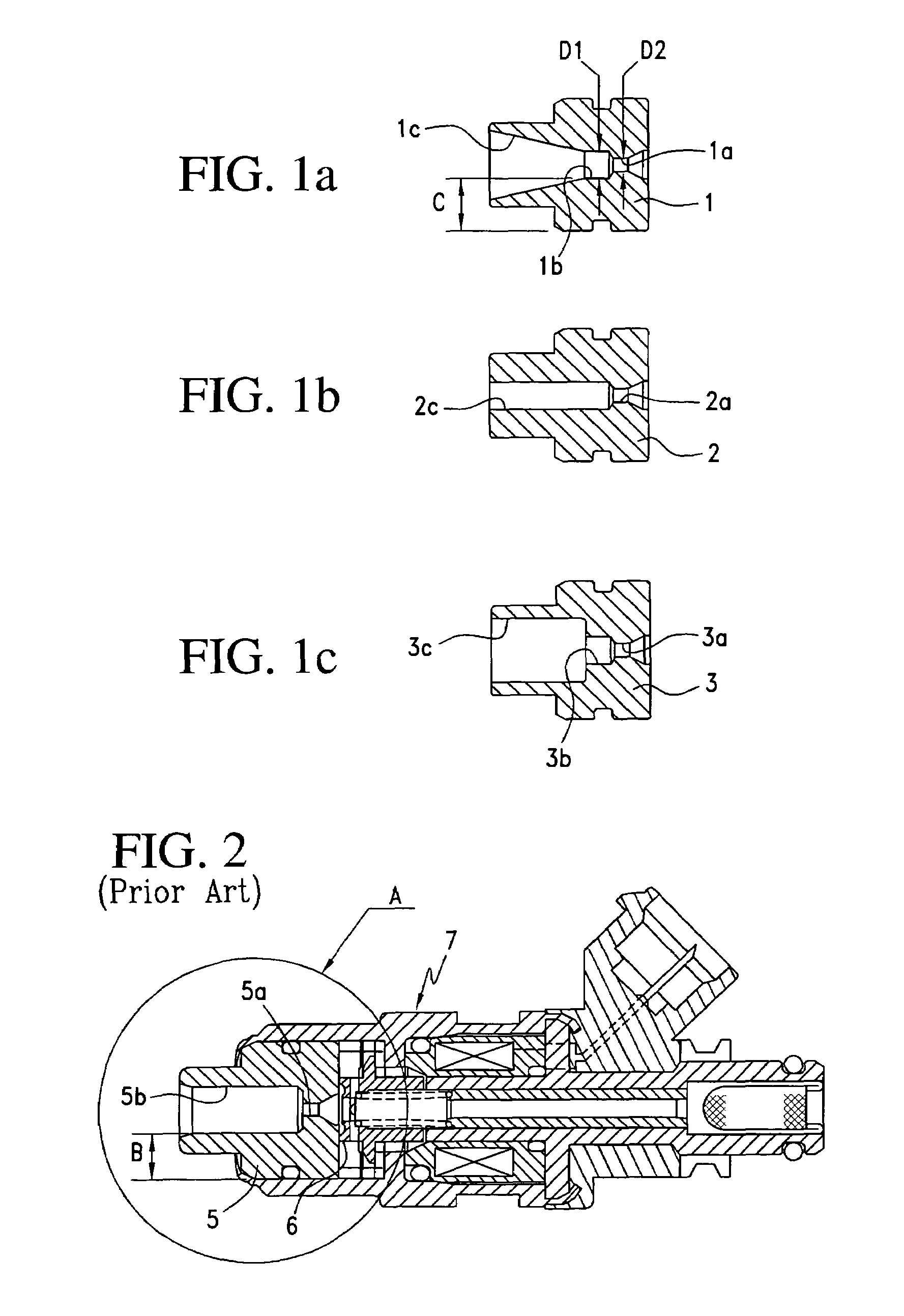
The present invention provides fuel injectors that prevent leakage of noise caused by contact of the valve with the valve seat. This is achieved by designing a jet opening downstream channel with a smaller diameter, which results in a greater wall thickness of the valve seat. This prevents noise from leaking through the valve seat and into the outside of the fuel injector.

Problems solved by technology

Such noise is typically caused by contact of the valve with the valve seat.

Method used


Image

  • Fuel injectors
  • Fuel injectors

Examples


Embodiment Construction

[0015]As one aspect of the present teachings, the diameter of the jet opening downstream channel of the representative fuel injector may be designed so as to ensure the diffusability of the fuel exhausted from the jet opening, as well as preventing leakage of noise to the outside through the valve seat.

[0016]Especially, the jet opening downstream channel may preferably have a region in which its diameter is substantially double the diameter of the jet opening. The diameter of the jet opening downstream channel may have substantially double the diameter of the jet opening at least in a region right below the jet opening.

[0017]Preferably, the length of the jet opening downstream channel along its longitudinal axis may be substantially the same as or larger than the diameter of the jet opening downstream channel. As a result, the leakage of noise to the outside can be more effectively prevented.

[0018]Further, as another aspect of the present invention, the representative fuel injector ...


PUM


Abstract

It is, accordingly, an object of the present teachings to provide fuel injectors that can prevent leakage of noise, which is caused by contact of the valve with the valve seat, to the outside of the fuel injector. a representative injector may comprise a fuel passage, a valve, a valve seat, a jet opening and a jet opening downstream channel. The valve is disposed on the fuel passage and the valve seat receives the valve. The jet opening is formed in the valve seat and through which fuel is exhausted. The jet opening may be opened when the valve is moved apart from the valve seat. The jet opening downstream channel extends downstream from the jet opening through the valve seat and communicates the jet opening to the outside. The diameter of the jet opening downstream channel may be arranged and adapted such that the valve seat has a wall thickness to prevent leakage of noise to the outside through the valve seat. Because the diameter of the jet opening downstream channel is designed to be smaller and the wall thickness of the valve seat is designed to be greater, the representative injector can effectively prevent leakage of noise to the outside through the valve seat.

Description

BACKGROUND OF THE INVENTION[0001]1. Field of the Invention[0002]The present invention relates to fuel injectors utilized in an internal combustion engines and more particularly, to fuel injectors which can reduce valve noise during the operation.[0003]2. Description of the Related Art[0004]An example of a known fuel injector for an internal combustion engine is disclosed in Japanese Laid-Open Patent Publication No. 2000-240525 and is reproduced in FIG. 2. FIG. 2 shows a sectional view of a fuel injector 7 for an internal combustion engine. The fuel injector 7 is designed to lift an armature, which forms a valve 6, by excitation of a coil and exhaust (inject) fuel through a jet opening 5a. Further, the fuel injector 7 has a jet opening downstream channel 5b that extends downstream from the jet opening 5a through a valve seat 5. The fuel injector 7 is configured such that fuel exhausted from the jet opening 5a can be diffused as much as possible into the engine and atomized.[0005]Howe...

Claims


Application Information

Patent Timeline
Patent Type & Authority Patents(United States)
IPC IPC(8): F02M61/00F02M51/06F02M61/18
CPCF02M61/18F02M51/0667
Inventor KAWAZOE, HIROSHIMAKIMURA, TOSHIRO
Owner AISAN IND CO LTD
Learn More