Resilient shielding member for device

a shielding member and resilient technology, applied in the direction of coupling device connections, electrical apparatus casings/cabinets/drawers, metallic containers, etc., can solve the problem of noise superimposed on a current flowing in the terminal fittings leaking to the outsid

Active Publication Date: 2018-11-20
AUTONETWORKS TECH LTD +2
View PDF11 Cites 0 Cited by
  • Summary
  • Abstract
  • Description
  • Claims
  • Application Information

AI Technical Summary

Benefits of technology

[0006]The waterproofing function component surrounds the conductive paths over the entire circumference while being held in close contact with the first and second shield cases in a liquid-tight manner. Thus, adhesion of moisture to the conductive paths is prevented. Further, the shielding component surrounds the conductive paths over the entire circumference while being conductively held in contact with the first and second shield cases. Thus, leakage of noise superimposed on a current flowing in the conductive paths is prevented. Since the resilient shielding member for the device is formed by integrating the waterproofing component and the shielding component, assembling workability is excellent.

Problems solved by technology

Thus, noise superimposed on a current flowing in the terminal fittings leaks to the outside.

Method used


Image

  • Resilient shielding member for device
  • Resilient shielding member for device
  • Resilient shielding member for device

Examples


Embodiment Construction

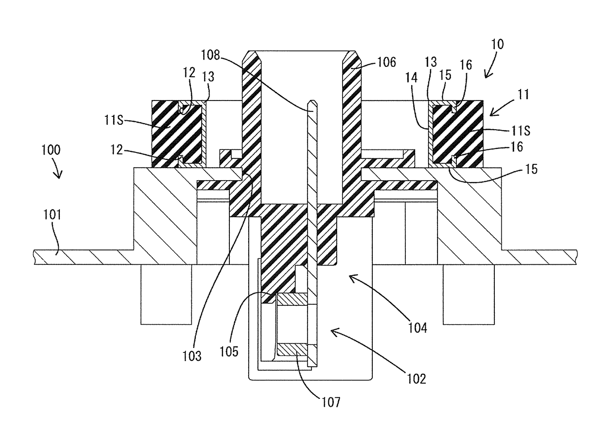
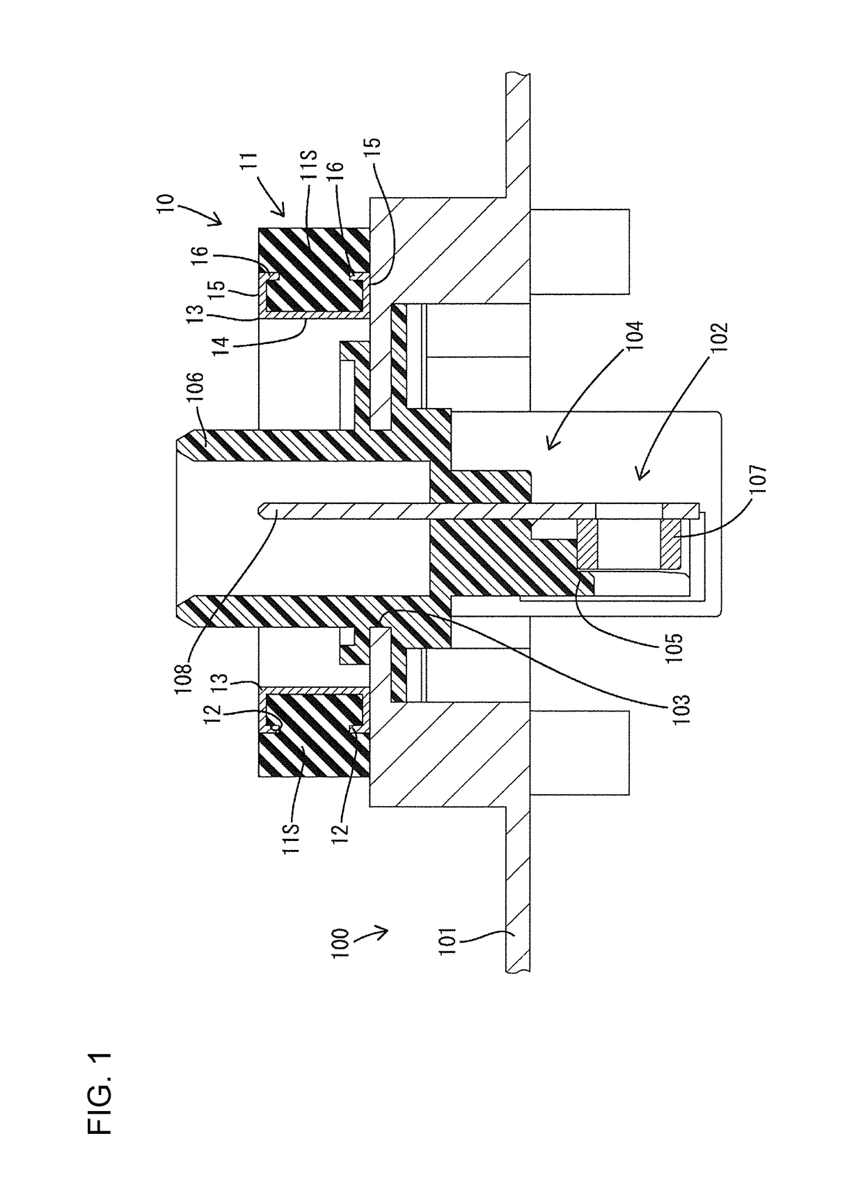
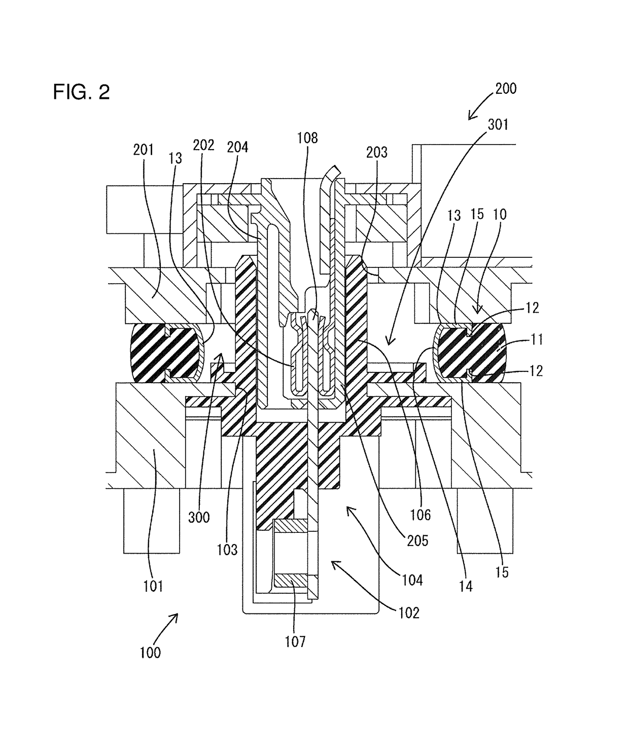
[0028]A first embodiment of the invention is described with reference to FIGS. 1 to 3. A resilient shielding member for a device 10 of the first embodiment is a composite function member provided in a vehicle configured to travel utilizing electric power such as an electric or hybrid vehicle and interposed between a motor 100 (first electrical device as claimed) and an inverter device 200 (second electrical device as claimed).

[0029]The motor 100 includes a motor body (not shown) for generating a rotational drive force by energization, a conductive (metallic) motor case 101 (first shield case as claimed) surrounding the motor body, and a plurality of first terminal fittings 102 (conductive paths as claimed) conductively connected to the motor body. A first opening 103 allowing communication between the inside and outside of the motor case 101 is formed in a horizontal upper surface wall constituting the motor case 101.

[0030]A first terminal block 104 made of synthetic resin is fixed ...


PUM


Abstract

A resilient shielding member for a device (10) is disposed in a facing space (300) between a conductive motor case (10) of a motor (100) and an inverter case (201) of an inverter device (200). The resilient shielding member surrounds first terminal fittings (102) and second terminal fittings (202) connecting the motor (100) and the inverter device (200) over the entire circumference and is formed by integrating a waterproofing component (11) configured to resiliently contact the motor case (101) and the inverter case (201) in a liquid-tight manner over the entire circumference and a shielding component (13) configured to conductively contact the motor case (101) and the inverter case (201).

Description

BACKGROUNDField of the Invention[0001]The invention relates to a resilient shielding member for a device.Description of the Related Art[0002]Japanese Unexamined Patent Publication No. 2007-280913 discloses an inverter device and a motor that are connected by connectors of a direct connection type without using a wiring harness in an electric or hybrid vehicle. The inverter device and the motor are accommodated respectively in individual metal casings and the connector is fixed to each metal casing. The connectors are mated and connected with the inverter device arranged near the motor. In this way, the miniaturization of the entire device including the inverter device and the motor is realized.[0003]In electric and hybrid vehicles, an inverter device and a motor need to be arranged with a clearance defined therebetween to avoid interference due to vibration during travel. However, terminal fittings on the inverter device side and terminal fittings on the motor side are exposed if th...

Claims


Application Information

Patent Timeline
Patent Type & Authority Patents(United States)
IPC IPC(8): H05K5/00H05K9/00H01R13/533H05K5/06
CPCH05K5/069H05K9/0049H01R13/533H05K9/0015H01R13/6584
Inventor NAONO, HIDEO
Owner AUTONETWORKS TECH LTD
Why Eureka
Try Eureka