Image reading device

a reading device and image technology, applied in the direction of circuit bendability/stretchability, printed circuit aspects, printed circuits, etc., can solve the problems of significant problem, above-described conventional technology, etc., to prevent noise leakage, reduce and reduce the effect of stress applied to the transmitting layer

Active Publication Date: 2017-04-18
KONICA MINOLTA INC
View PDF8 Cites 0 Cited by
  • Summary
  • Abstract
  • Description
  • Claims
  • Application Information

AI Technical Summary

Benefits of technology

[0012]In the image reading device in the above-described aspect, a part of the FFC is bent into the U-shape and a reversely bent portion is generated depending on a position of the scanning unit. Therefore, a part of the FFC is repetitively reversed between a bend and a reverse bend by reading operation. However, since the stress adjusting layer is provided on the FFC, a position of the transmitting layer in a thickness direction structure of the FFC is brought closer to the center. Therefore, stress applied to the transmitting layer is small even when the bend of the FFC is repetitively reversed. Therefore, the FFC has a long life.
[0013]In the image reading device in the above-described aspect, the shielding layer or the impedance adjusting layer is preferably provided on a surface on an outer side of the U-shaped bend of the FFC. This is advantageous for preventing noise from leaking.
[0014]In the image reading device in the above-described aspect, a bending neutral plane in an entire thickness of the FFC including the stress adjusting layer, the shielding layer, or the impedance adjusting layer is preferably located in the transmitting layer. By realizing this by adjusting a thickness of the stress adjusting layer, the stress of the bend applied to the transmitting layer may be more certainly decreased.

Problems solved by technology

However, the above-described conventional technology has a following problem.
Especially, when the FFC 102 in which a shielding layer or an impedance adjusting layer is stacked on one surface side of a transmitting layer thereof is used, this problem is significant.

Method used


Image

  • Image reading device
  • Image reading device
  • Image reading device

Examples


first example

Impedance adjusting layer 38: thickness of approximately 120 μm, relative permittivity of approximately 2.1

Shielding layer 39: thickness of approximately 29 μm, silver deposition SN / HM type

second example

Impedance adjusting layer 38: thickness of approximately 110 μm, relative permittivity of approximately 2.3

Shielding layer 39: thickness of approximately 45 μm, aluminum solid shield (conductive adhesive material)

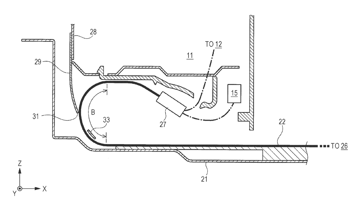
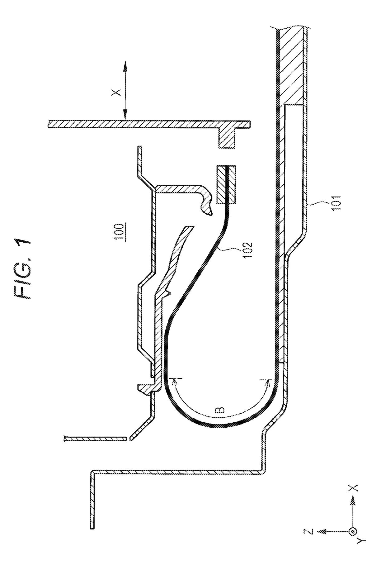
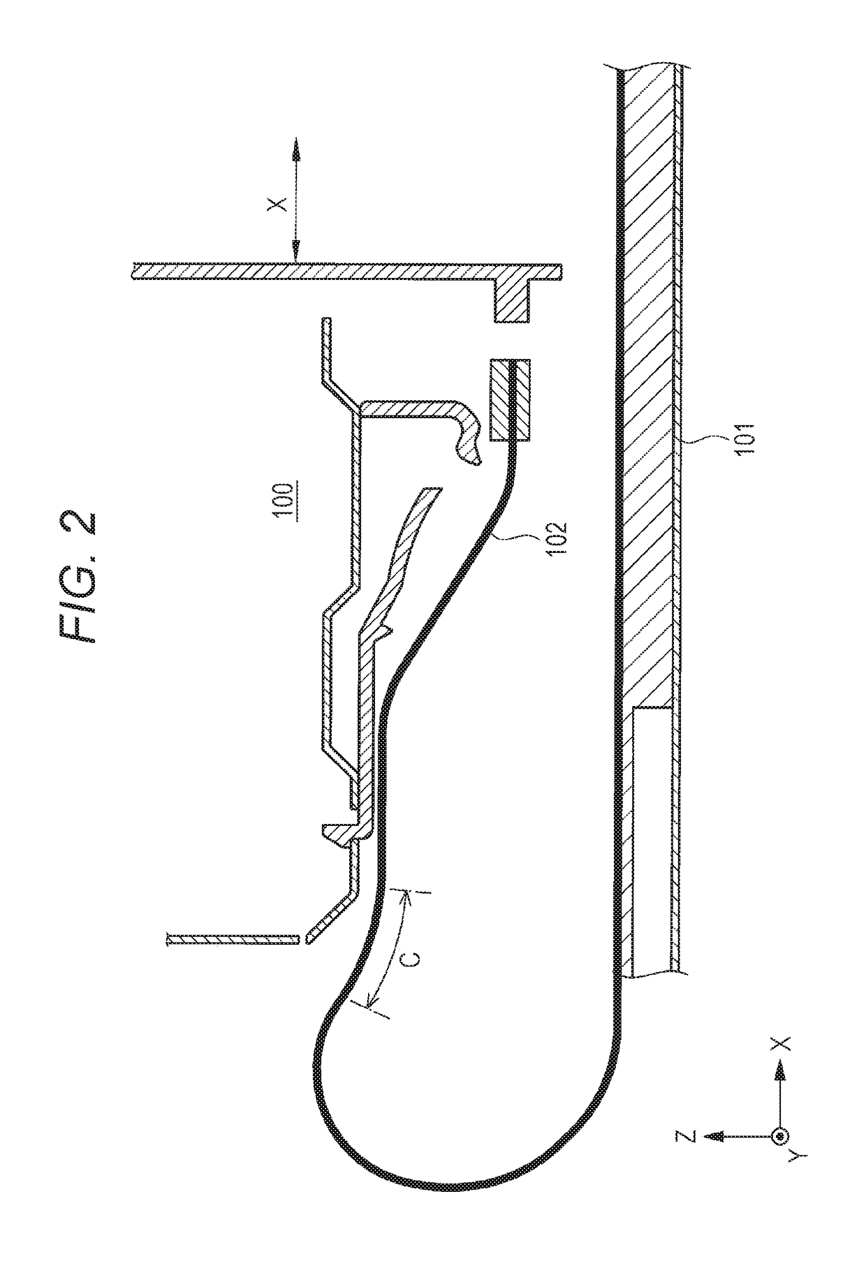
[0053]The PET layer 42 having a thickness of 50 pm was used; the PET layer 42 was provided on an entire area closer to the connector 27 than the bent portion 26. However, the PET layer 42 was not provided on the bent portion 26 itself. In configurations of the test examples, when the position of the bending neutral plane was checked by CAE analysis, this was located within the range of the conductive wire 35 in both cases. In both of them, 14,000,000 sheets or more were able to be read. Disconnection occurred in the transmitting unit 34 when approximately 140,000 sheets were read without the PET layer 42 and the elastic sheet member 29 used (comparative example), so that improvement by two orders of magnitude was realized. Normal request specification is approximately 380,0...


PUM

PropertyMeasurementUnit
stressaaaaaaaaaa
widthaaaaaaaaaa
widthaaaaaaaaaa

Abstract

An image reading device which reads an image to obtain an image signal includes: a scanning unit; a chassis member; a control unit provided in a position which does not move together with the scanning unit; and a flexible flat cable which connects the scanning unit to the control unit, includes one end attached to a side of the chassis member and a position other than the one end fixed to a position which does not move with the scanning unit, includes a range closer to the one end than the fixed position parallel to a moving direction of the scanning unit, and is arranged to extend from the one end to one side, be bent into a U-shape, enter between the scanning unit and the chassis member, and reach the fixed position, and the flexible flat cable includes a transmitting layer, a shielding layer, and a stress adjusting layer.

Description

[0001]The entire disclosure of Japanese Patent Application No. 2015-089403 filed on Apr. 24, 2015 including description, claims, drawings, and abstract are incorporated herein by reference in its entirety.BACKGROUND OF THE INVENTION[0002]Field of the invention[0003]The present invention relates to an image reading device which reads an image of an original to obtain an image signal. In more detail, the present invention relates to the image reading device which performs place-and-image reading of the image of the original which is statically placed by a scanning unit moving in a longitudinal direction of the original.[0004]Description of the Related Art[0005]JP 2012-108424 A discloses an example of this type of conventional image reading device. In the image reading device disclosed in JP 2012-108424 A, a reading unit elongated. in a main scanning direction reciprocates in a sub scanning direction to read the image of the original. Herein, communication of an electrical signal betwe...

Claims


Application Information

Patent Timeline
Patent Type & Authority Patents(United States)
IPC IPC(8): H04N1/00H05K1/00H04N1/04
CPCH04N1/0083H04N1/00795H04N1/04H05K1/00H04N2201/0049H04N2201/0081H05K1/0281H05K1/147H05K2201/0145H05K2201/2009
Inventor TSUJIHARA, KIYOHITOUMEDA, SHIROHIGUCHI, YUKI
Owner KONICA MINOLTA INC
Why Eureka
Try Eureka