Compressor of turbo machine and its compressor wheel

a compressor wheel and turbo machine technology, which is applied in the direction of liquid fuel engines, vessel construction, marine propulsion, etc., can solve the problems of high stress amplitude applied to the compressor wheel b>16/b>, and less stress on the compressor wheel. , the effect of reducing the weigh

Inactive Publication Date: 2005-02-24
KOMATSU LTD
View PDF5 Cites 22 Cited by
  • Summary
  • Abstract
  • Description
  • Claims
  • Application Information

AI Technical Summary

Benefits of technology

[0023] The fitting hole or aperture for coupling with the shaft need not be disposed in the compressor wheel main body portion. As a result, the stress acting on the compressor wheel becomes small and breaking becomes less even when the compressor wheel is rotated at a high number of revolutions.
[0024] The compressor wheel is formed in many cases of a material having a lower intensity than the shaft to reduce the weight. Therefore, when the male screw portion of the compressor wheel is rendered thick, the problem that the male screw portion of the compressor wheel is particularly likely to be broken becomes small and overall durability can be improved.
[0025] When the rotation balance of the compressor wheel and the turbine wheel is individually adjusted and these wheels are assembled, a centering error after assembly becomes small. Therefore, the frequency of re-adjustment of the rotation balance of the compressor of the turbo machine becomes small.
[0026] Members for sealing air and oil need not be disposed separately, and air and oil can be sealed with a compact construction.
[0027] It is also possible to support the thrust bearing with a simple construction and to effectively bear the force in the thrust direction that acts on the shaft.
[0028] Because breaking of the compressor wheel becomes more difficult to occur and durability can be improved, the pressure ratio of the turbo charger using this compressor wheel can be increased.

Problems solved by technology

However, the prior art technology shown in FIG. 8 is not free from the following problem.
As a result, the stress amplitude applied to the compressor wheel 16 becomes high and breaking is more likely to occur.
The prior art technology is not yet sufficient and a compressor wheel 16 having higher durability has been desired.

Method used


Image

  • Compressor of turbo machine and its compressor wheel
  • Compressor of turbo machine and its compressor wheel
  • Compressor of turbo machine and its compressor wheel

Examples


Embodiment Construction

[0038] A preferred embodiment of the invention will be hereinafter explained in detail with reference to the accompanying drawings.

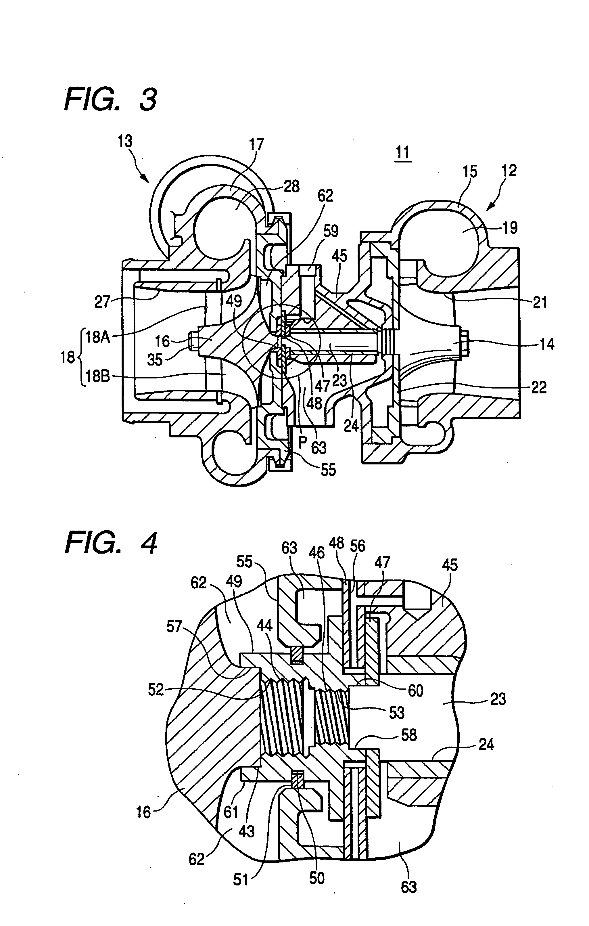
[0039] Referring to FIG. 3, an exhaust-side unit 12 includes an exhaust-side housing 15 and a turbine wheel 14 having a plurality of vanes and supported by a shaft 23.

[0040] The exhaust-side housing 15 has an exhaust inflow passage 19 for supplying an exhaust gas to the turbine wheel 14. The exhaust inflow passage 19 is formed into an annular shape in such a manner as to encompass the outer periphery of the turbine wheel 14 and is connected to an engine exhaust flow passage through which the exhaust gas emitted from an engine, not shown, flows. The exhaust-side housing 15 has also an exhaust outflow port 21 for emitting the exhaust gas after imparting energy to the turbine wheel 14. The exhaust outflow port 21 is formed substantially into a cylindrical shape that is concentric with the center of revolution of the turbine wheel 14. An opening on the opp...


PUM


Abstract

The invention provides a compressor of a turbo machine and its compressor wheel that do not easily undergo breaking even when rotated at a high number of revolutions. The compressor of the turbo machine includes a male screw portion integrally formed on a main body portion of the compressor wheel and a male screw portion disposed at a distal end of a shaft for driving the compressor wheel that are coupled with each other through a sleeve equipped at one of the ends thereof with a female screw portion capable of meshing with the male screw portion of the compressor wheel and at the other end with a female screw portion capable of meshing with the male screw portion of the shaft.

Description

BACKGROUND OF THE INVENTION [0001] 1. Field of the Invention [0002] This invention relates to a compressor of a turbo machine and its compressor wheel. [0003] 2. Description of the Related Art [0004] A compressor of a turbo machine of the type that is rotated by a turbine wheel via a shaft by utilizing energy of an exhaust gas as means for increasing an intake amount of an engine by compressing air and drives a centrifugal type compressor wheel coupled with a shaft is known as a turbo charger. [0005]FIG. 7 is a sectional side view of the turbo charger 11 according to the prior art. The turbo charger 11 includes an exhaust-side unit 12 for taking out energy of revolution from the exhaust gas of an engine and an intake-side unit 13 for compressing air by this energy of revolution and sending compressed air into the engine. [0006] A turbine wheel 14 is imparted with energy and is rotated by the exhaust gas inflowing from an exhaust inflow passage 19. A centrifugal type compressor wheel...

Claims


Application Information

Patent Timeline
Patent Type & Authority Applications(United States)
IPC IPC(8): F02B39/00F04D29/00F04D29/056F04D29/26F04D29/28F16C17/04F16C33/74F16D1/06
CPCF04D29/266F16C2360/24F16D1/06F04D29/284F02B39/00F04D29/00
Inventor NISHIYAMA, TOSHIHIKOINABA, KEIICHI
Owner KOMATSU LTD
Why Eureka
Try Eureka