Functional laminate and functional structure

a functional laminate and functional technology, applied in the field of functional laminates, can solve the problems of inability to meet the needs of use, so as to achieve the effect of reducing deformation and stress inside the functional laminate, reducing damage, and reducing damag

Inactive Publication Date: 2011-10-20
DEXERIALS CORP
View PDF13 Cites 23 Cited by
  • Summary
  • Abstract
  • Description
  • Claims
  • Application Information

AI Technical Summary

Benefits of technology

[0020]With the functional laminate according to the embodiment, the functional layer is sandwiched between the first support and the second support with the first resin layer and the second resin layer interposed respectively between the functional layer and the first and second resin layers. Further, the first support and the second support have the elastic moduli larger than those of the first resin layer and the second resin layer. Thus, the functional layer is positioned between two supports, which are comparatively hard to deform, in such a state as wrapped with cushioning materials. Accordingly, even when an external force is exerted on the functional laminate, the external force is first borne by the first support and the second support, which are comparativ

Problems solved by technology

In the process of manufacturing the directional reflector or the semi-reflection (half-m

Method used


Image

  • Functional laminate and functional structure
  • Functional laminate and functional structure
  • Functional laminate and functional structure

Examples


first embodiment

[0056]The first embodiment is described in connection with examples of a functional laminate.

[0057][Functional Laminate]

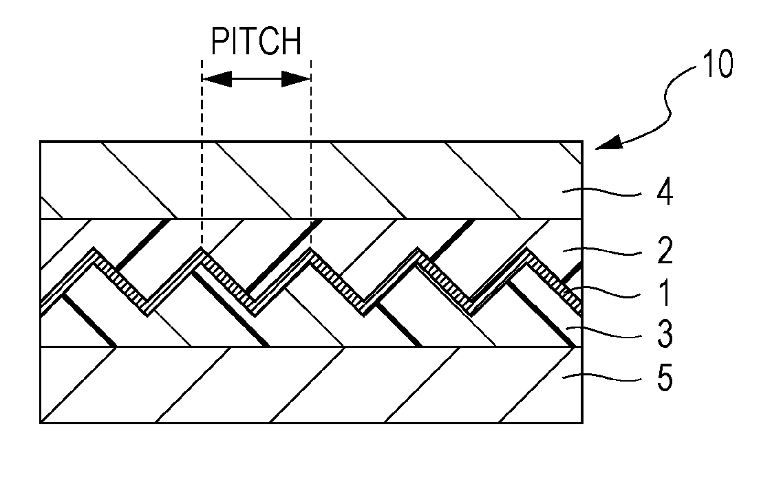
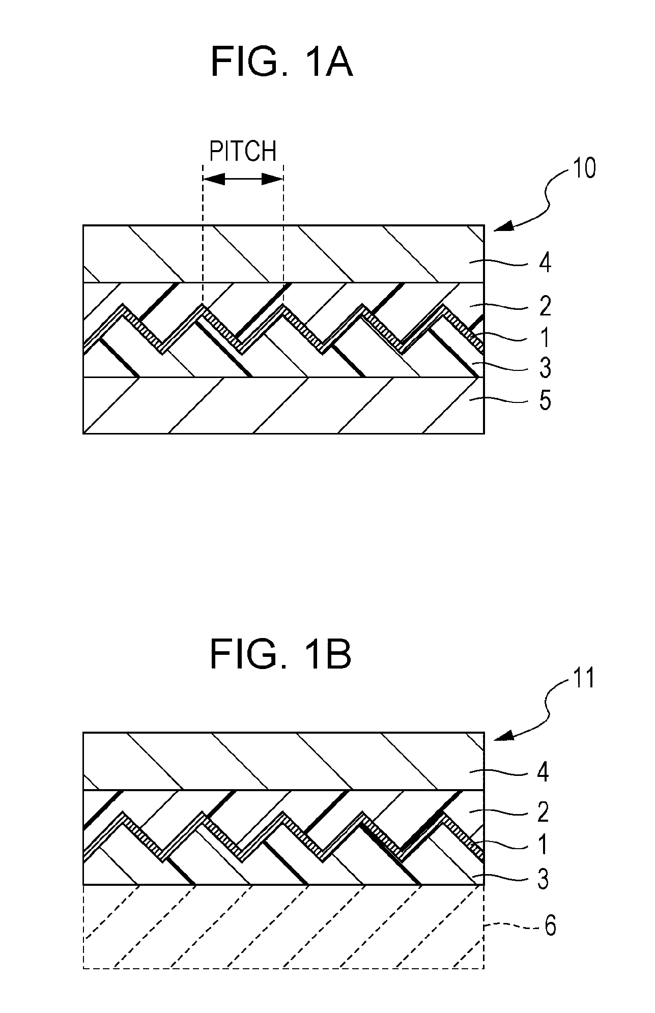
[0058]FIG. 1A is a sectional view illustrating the structure of a functional laminate 10 according to the first embodiment. The functional laminate 10 includes a functional layer 1, a first resin layer 2 and a second resin layer 3 disposed in close contact with two principal surfaces of the functional layer 1, respectively, and sandwiching the functional layer 1 therebetween, a first support 4 disposed in contact with one surface of the first resin layer 2 on the side oppositely away from the other surface thereof, which is in contact with the functional layer 1, and a second support 5 disposed in contact with one surface of the second resin layer 3 on the side oppositely away from the other surface thereof, which is in contact with the functional layer 1. The functional layer 1 includes an inorganic layer formed in a predetermined three-dimensional shape, and deve...

second embodiment

[0154]A second embodiment will be described below in connection with examples of a functional structure. The functional laminate according to the embodiment can be typically affixed to, e.g., a glass, thereby constituting a functional structure, such as a window member. Further, the functional laminate according to the embodiment can be utilized so as to constitute functional structures in the form of, e.g., various interior and exterior members. Those functional structures include not only fixedly installed members such as walls and roofs, but also a member capable of changing an extent at which the optical functional laminate develops the function in its application, as appropriate, depending on changes of the seasons and time, etc. One practical example of the latter member is a window blind (shade), which is constituted by dividing the optical functional laminate into plural elements and assembling the plural elements such that the amount by which incident light is transmitted t...

first application example

[0156]A first application example is described in connection with the case of applying the functional laminate to a window blind (shade), i.e., one example of a solar shading device capable of adjusting an extent at which the incident light is to be blocked, by changing an angle of a solar shading member group that includes a plurality of solar shading members.

[0157]FIG. 15A is a perspective view illustrating the structure of a window blind (shade) 80 as one example of the solar shading device. The window blind 80 includes a head box 83, a slat group (solar shading member group) 82 made up of plural slats (blades) 81, and a bottom rail 84. The head box 83 is disposed above the slat group 82. Rise-and-fall chords 85 and a rise-and-fall operating chord 86 are extended downward from the head box 83, and the bottom rail 84 is suspended at lower ends of the chords 85. The slats 81 serving as the solar shading members are each formed in a slender rectangular shape and are supported by lad...


PUM


Abstract

A functional laminate includes a functional layer including an inorganic layer formed in a predetermined three-dimensional shape, first and second resin layers disposed in close contact with two principal surfaces of the functional layer, respectively, and sandwiching the functional layer therebetween, and first and second supports disposed respectively in contact with one surface of the first resin layer on a side oppositely away from the other surface thereof, which is contacted with the functional layer, and with one surface of the second resin layer on a side oppositely away from the other surface thereof, which is contacted with the functional layer. The first and second supports have elastic moduli larger than those of the first and second resin layers. One of the first and second supports is omissible when the one support is replaced with an external support having an elastic modulus not smaller than that of the one support.

Description

CROSS REFERENCES TO RELATED APPLICATIONS[0001]The present application claims priority to Japanese Patent Application JP 2010-081465 filed on Mar. 31, 2010, the entire contents of which is hereby incorporated by reference.BACKGROUND[0002]The present disclosure relates to a functional laminate suitably used as, e.g., an optical functional film, which selectively and directionally reflects light in a specific wavelength range, but which transmits light other than the specific wavelength range therethrough. The present invention also relates to a functional structure including the functional laminate.[0003]Recently, an optical layer partly absorbing or reflecting the sunlight has been coated on architectural glasses for high-rise buildings and housings, vehicular window glasses, etc. in increasing cases. Such an optical layer serves to prevent the indoor temperature from rising overly with the sunlight coming into the indoor through windows. Optical energy coming from the sun is primari...

Claims


Application Information

Patent Timeline
IPC IPC(8): B32B3/00
CPCG02B5/045Y10T428/24479G02B5/208G02B5/124
Inventor ITO, HIROYUKI
Owner DEXERIALS CORP
Why Eureka
Try Eureka