Combined steel oil control ring

a technology of oil control ring and steel plate, which is applied in the direction of brake systems, machines/engines, transportation and packaging, etc., can solve the problems of easy wear and tear of contours, increased consumption of lubricating oil, and easy wear and tear of portions for forming fine saw-tooth contours on the surface of ear portions. , to achieve the effect of preventing wear and shortening the life of the di

Active Publication Date: 2006-05-16
NIPPON PISTONRING CO LTD
View PDF3 Cites 25 Cited by
  • Summary
  • Abstract
  • Description
  • Claims
  • Application Information

AI Technical Summary

Benefits of technology

[0010]The arrangement as described above has the outstanding advantage that, with the up-and-down contours formed circumferentially along the radially external circumferential surface of the ear portions of the spacer expander that the side rails contact, the side rails are prevented from circumferentially rotating relatively to the spacer expander and also the up-and-down contours themselves are prevented from wearing out. Such an advantage is obtained by causing both the flat regions within each ear portion together to have an aggregate circumferential width within a range of 30-70% and by causing the groove regions within each ear portion together to have an aggregate circumferential width within the range of 70-30%, of an entire circumferential width of each ear portion.
[0011]As for the wear of the dies, when the groove regions of each of the ear portions of the up-and-down contours have, for example, a depth of around 0.05 mm and a circumferential width of around 0.2 mm, then, the protruding regions of the die for forming the groove regions of the up-and-down contours have a width of around 0.2 mm and a height of around 0.05 mm, whereby the shortening of the lifespan of the die may be relatively small due to wear and tear.

Problems solved by technology

The arrangement described in the publication above has a problem in that, because the up-and-down contours on the radially external circumferential surfaces of the ear portions are as fine, the contours easily wear out.
When the contours wear out, not only do the side rails tend to circumferentially rotate relatively to the spacer expander, but also the capability of the side rails to follow up the cylinder of the internal combustion engine is caused to deteriorate, which in turn increases consumption of the lubricating oil.
The arrangement described in the publication above also has another problem in that metal molds, or dies, having protruding portions for forming the fine saw-tooth contours on the surfaces of the ear portions easily wear out.
This is because each of the protruding portions of the die for forming the fine grooves of the saw tooth contours has a very narrow width as narrow as 12.5-125 μm, which, in turn, causes a deterioration or shortening of the life of the dies .

Method used


Image

  • Combined steel oil control ring
  • Combined steel oil control ring
  • Combined steel oil control ring

Examples


Embodiment Construction

[0019]Hereunder, the present invention is described more in detail according to embodiments thereof, referring to drawings attached hereto.

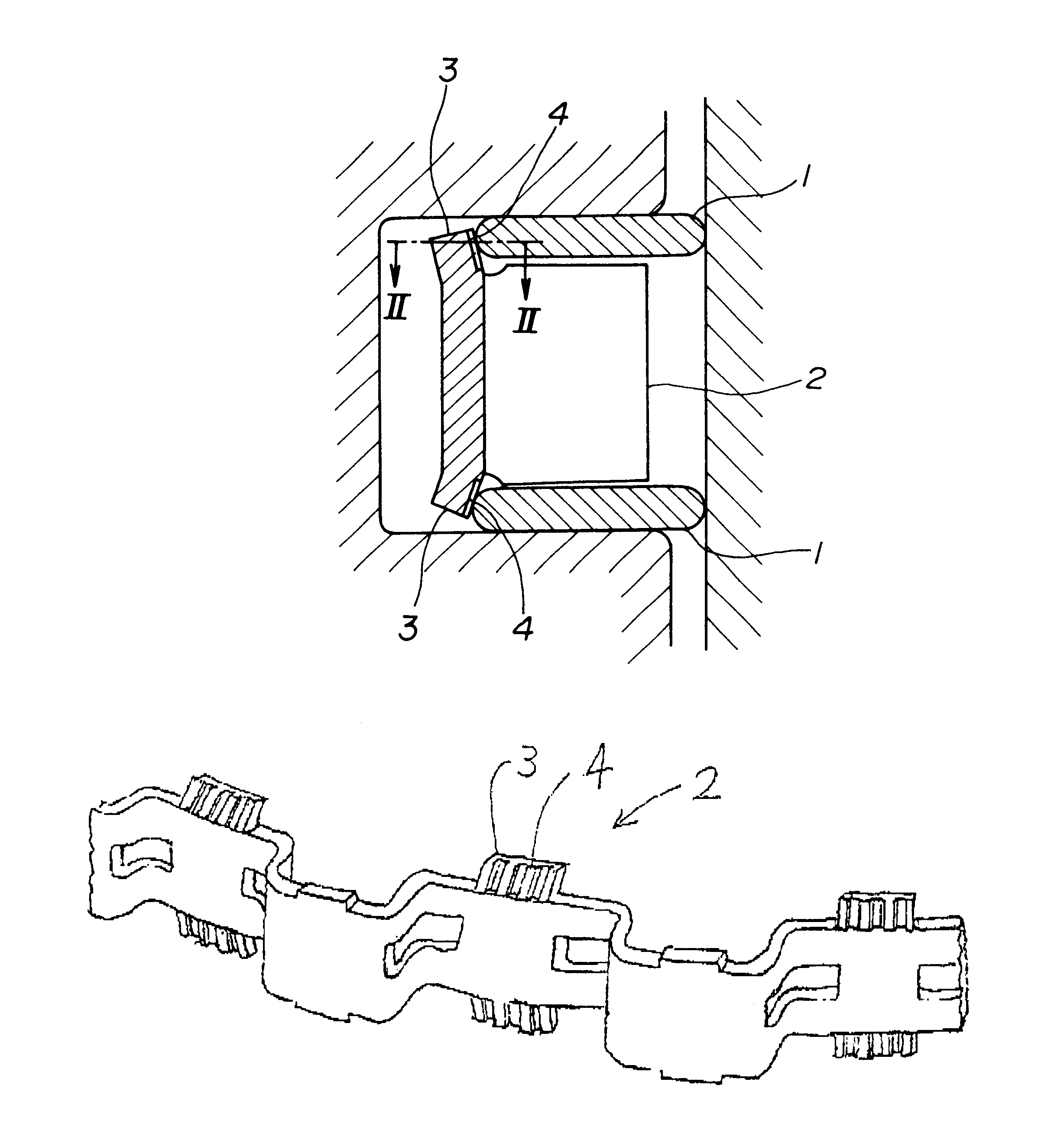
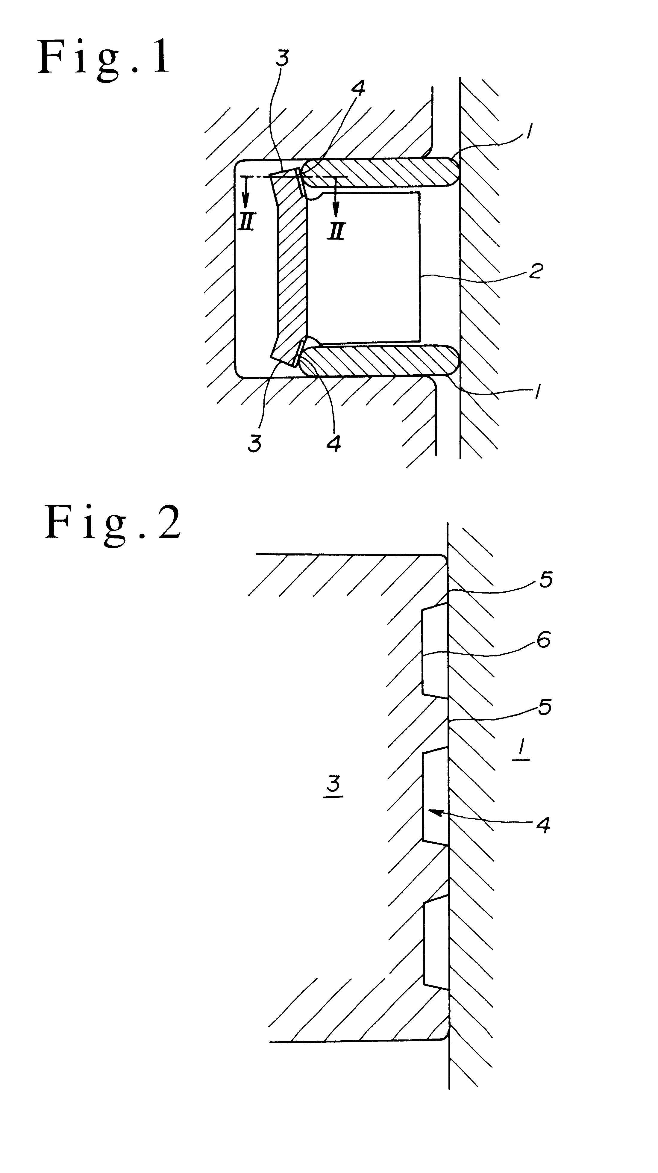
[0020]FIG. 1 is a cross-sectional view of a combined steel oil control ring according to an embodiment of the present invention, and FIG. 2 is an enlarged cross-sectional view along arrow lines II—II of FIG. 1.

[0021]As shown in FIG. 1, the combined steel oil control ring, according to the present invention, has steel side rails 1 and a steel spacer expander 2, having a wave-like shape circumferentially extending within a radial plane. The spacer expander 2 includes ear portions 3 axially protruding from the body of the spacer expander 2 for contacting the side rails 1. The ear portions 3 are substantially, equally spaced with each other along the internal circumferential portion of the spacer expander 2. The ear portions 3 have a radially external circumferential surface, respectively, for contacting the side rails 1, and are adapted to press the...


PUM


Abstract

A combined steel oil control ring is provided which has steel side rails and a steel spacer expander. The spacer expander includes ear portions for contacting the side rails. The ear portions are substantially equally spaced with respect to each other along the internal circumferential portion of the spacer expander. The ear portions have radially external circumferential surfaces adapted to press the side rails radially outwardly by using the resilient force caused by the spacer expander. The spacer expander has up-and-down contours formed circumferentially along the radially external circumferential surface, for preventing the side rails from circumferentially rotating relatively to the spacer expander. The up-and-down contours each include at least two axially extending groove regions and at least three axially extending flat regions. The groove regions and flat regions are dimensioned to extend the life span of the contours and the dies.

Description

[0001]This nonprovisional application claims priority under 35 U.S.C. § 119(a) on Patent Application No. 2001-350135 filed in JAPAN on Nov. 15, 2001, which is herein incorporated by reference.FIELD OF THE INVENTION[0002]The present invention relates to a combined steel oil control ring for internal combustion engines including steel side rails and a steel spacer expander.BACKGROUND OF THE INVENTION[0003]A conventional combined steel oil control ring typically has a construction that combines steel side rails and a steel spacer expander. The spacer expander includes protruding portions axially extending from the body of the spacer expander like an ear (hereinafter referred to as ear portions) for contacting the side rails. The ear portions are substantially, equally spaced with repect to each other along the internal circumferential portion of the spacer expander. The radially external circumferential surface of the ear portions is adapted to press the side rails radially outwardly b...

Claims


Application Information

Patent Timeline
Patent Type & Authority Patents(United States)
IPC IPC(8): F16J9/00F16J9/06F16J9/16
CPCF16J9/067
Inventor TAKAHASHI, AKIRATAKAHASHI, KAZUTOMO
Owner NIPPON PISTONRING CO LTD
Why Eureka
Try Eureka