
Torsion beam axle suspension

a technology of torsion beam and axle, which is applied in the direction of resilient suspension, interconnection system, vehicle components, etc., can solve the problems of vehicle stability decline, nonlinear elastic characteristics of torsion beam axle suspension, and vehicle stability drop, so as to increase the transverse rigidity of the mount, maintain continuous stability, and induce toe-in characteristics

Inactive Publication Date: 2006-05-16
HYUNDAI MOBIS CO LTD
View PDF12 Cites 21 Cited by
  • Summary
  • Abstract
  • Description
  • Claims
  • Application Information

AI Technical Summary

Benefits of technology

The present invention provides a torsion beam axle suspension that can induce toe-in characteristics and increase transverse rigidity of mounts when a transverse force is applied to a turning outer wheel at a rear suspension during cornering of a vehicle. This suspension system can maintain continuous stability of the vehicle and induce linear toe-in characteristics under any condition of hard and soft cornering. It is designed to secure sufficient transverse rigidity of mounts and achieve the desired toe-in characteristics.

Problems solved by technology

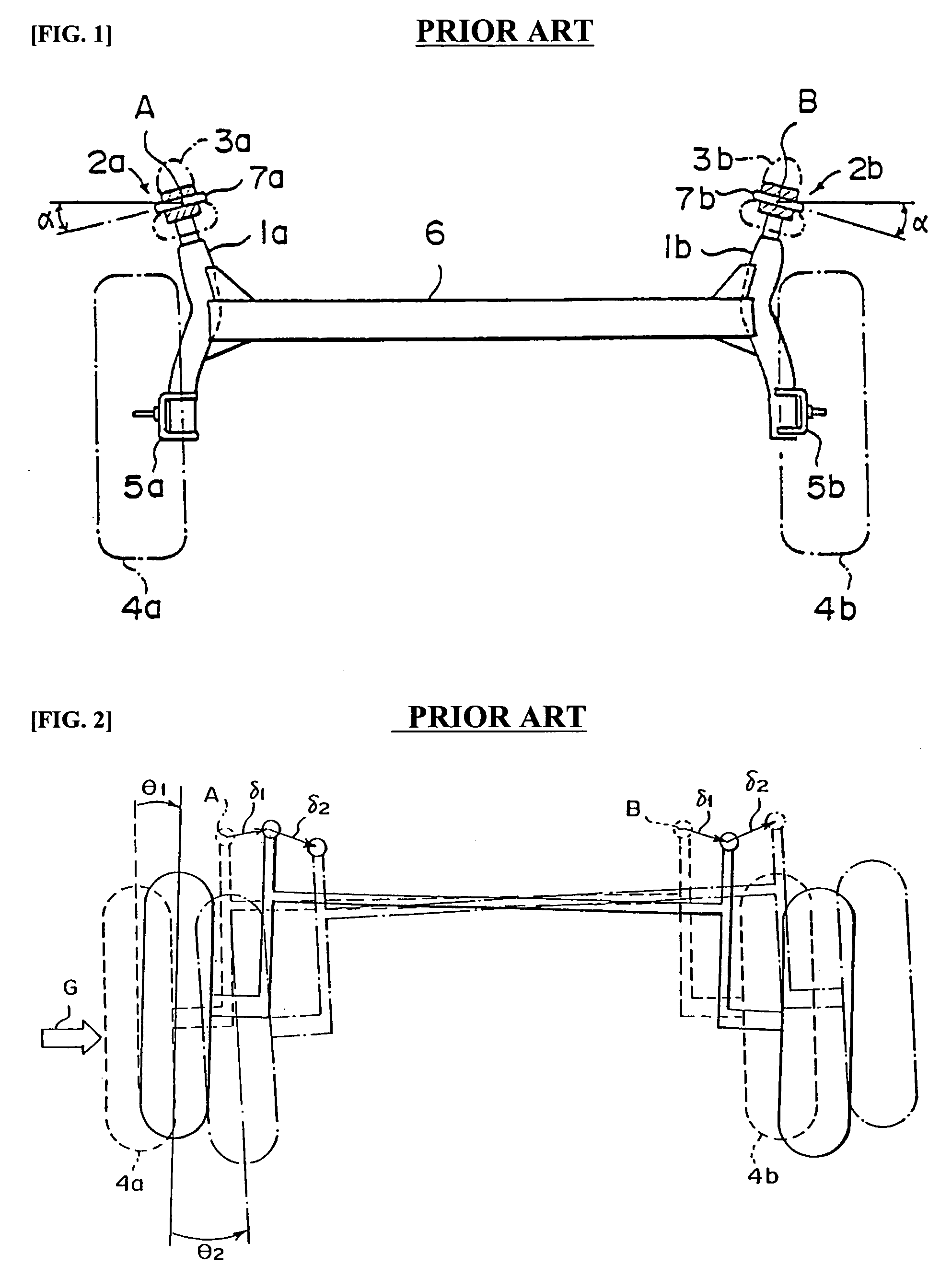
As a result, the bushings have nonlinear elastic characteristics.
However, the torsion beam axle suspension has the following problems.
As a result, the vehicle is decreased in stability.
Further, by forming circumferential holes in the mounting bushings, or press-fitting the resin plate into the formed holes, the bushings have nonlinear elastic characteristics.

Method used


Image

  • Torsion beam axle suspension
  • Torsion beam axle suspension
  • Torsion beam axle suspension

Examples


Embodiment Construction

[0031]A preferred embodiment of the present invention will now be described with reference to the accompanying drawings. In the following description, same drawing reference numerals are used for the same elements even in different drawings. The matters defined in the description such as a detailed construction are nothing but the ones provided to assist in a comprehensive understanding of the invention. Thus, it is apparent that the present invention can be carried out without those defined matters. Also, well-known functions or constructions are not described in detail since they would obscure the invention in unnecessary detail.

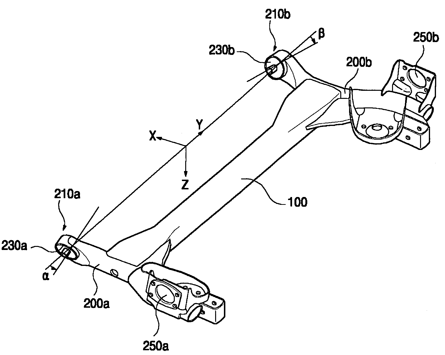
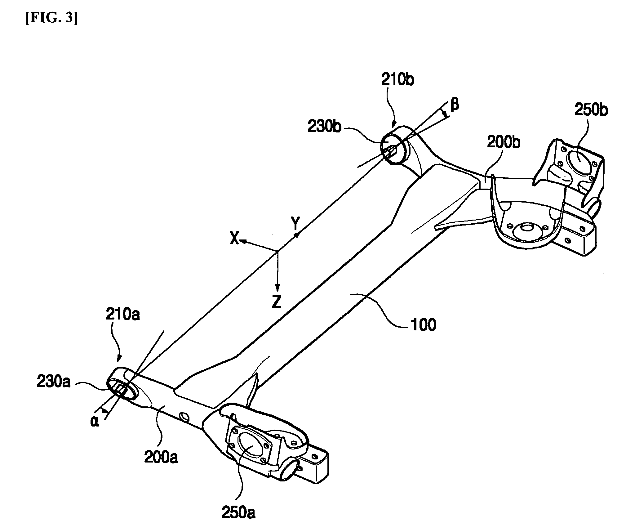
[0032]FIG. 3 is a perspective view illustrating a torsion beam axle suspension according to a preferred embodiment of the invention. FIG. 4a is a plan view illustrating a state in which the mounts of FIG. 3 are slanted along an X-Y axis, and FIG. 4b is a plan view illustrating a state in which the mounts of FIG. 3 are slanted along an X-Z axis. FIG. 5 show...


PUM


Abstract

In the torsion beam axle suspension of the present invention, by providing mounts formed on one end of each of trailing arms with a three-dimensional slant angle, when a transverse force is applied to a turning outer wheel at a rear suspension during cornering of a vehicle, toe-in characteristics are induced, and at the same time a transverse rigidity of the mounts can be increased.

Description

RELATED APPLICATIONS[0001]The present disclosure relates to subject matter contained in priority Korean Application No. 10-2003-0072095, filed on Oct. 16, 2003, which is herein expressly incorporated by reference in its entirety.BACKGROUND OF THE INVENTION[0002]1. Field of the Invention[0003]The present invention relates to a torsion beam axle suspension, and more particularly to a torsion beam axle suspension, in which a three-dimensional slant angle is given to mounts formed on one end of each of trailing arms.[0004]2. Description of the Related Art[0005]In general, a suspension in the vehicle is the apparatus, which is provided between a body and a wheel, for absorbing vibration or shock transmitted from a road surface during traveling to enhance stability such as turning stability, through connection of two linkages with one or multiple control arms, supporting by a spring and a shock absorber in upward and downward directions, and proper harmonization with high rigidity, flexib...

Claims


Application Information

Patent Timeline
Patent Type & Authority Patents(United States)
IPC IPC(8): B60G21/00B60G11/18B60B35/04B60G21/05
CPCB60B35/04B60G21/051B60G2204/1434B60G2200/21B60G11/18
Inventor KANG, JE-YOUNG
Owner HYUNDAI MOBIS CO LTD
Learn More