Catheter system having imaging, balloon angioplasty, and stent deployment capabilities, and method of use for guided stent deployment

a catheter system and balloon angioplasty technology, applied in the field of catheter systems, can solve the problems of small drawback of displaying images, and achieve the effect of rapid and convenient balloon angioplasty

Inactive Publication Date: 2006-05-16
BOSTON SCI SCIMED INC
View PDF66 Cites 142 Cited by
  • Summary
  • Abstract
  • Description
  • Claims
  • Application Information

AI Technical Summary

Benefits of technology

[0016]Another alternative catheter has one or more lumens in the proximal region, and two or more lumens in the distal region of the catheter, wherein at least one of the proximal lumens is in communication with at least one of the distal lumens. In this embodiment, the guidewire occupies one lumen in the distal region and can remain in place during imaging. This design offers the convenience of imaging using a movable imaging core in the second distal lumen while the guidewire remains in place in the first distal lumen. Operations using this design save time associated with withdrawing and advancing of instruments through the various lumens, but suffer the small drawback of displaying an image having artifacts associated with the presence of the guidewire positioned at one location in the ultrasound scan.
[0017]The catheter of the present invention will allow for performance of rapid and convenient balloon angioplasty and imaging for guided placement of a prosthetic device or stent within a diseased vessel, while minimizing the need to reposition the catheter body between procedures. Additionally, the distal end of the catheter will be relatively narrow to allow for movement of the catheter into restricted spaces of the patient's vascular system and particularly into narrow regions and stenoses within the coronary arteries. Further, the catheter of the invention enables stent deployment in combination with balloon angioplasty and imaging, and will allow for a guided stent placement procedure.

Problems solved by technology

Operations using this design save time associated with withdrawing and advancing of instruments through the various lumens, but suffer the small drawback of displaying an image having artifacts associated with the presence of the guidewire positioned at one location in the ultrasound scan.

Method used


Image

  • Catheter system having imaging, balloon angioplasty, and stent deployment capabilities, and method of use for guided stent deployment
  • Catheter system having imaging, balloon angioplasty, and stent deployment capabilities, and method of use for guided stent deployment
  • Catheter system having imaging, balloon angioplasty, and stent deployment capabilities, and method of use for guided stent deployment

Examples


Embodiment Construction

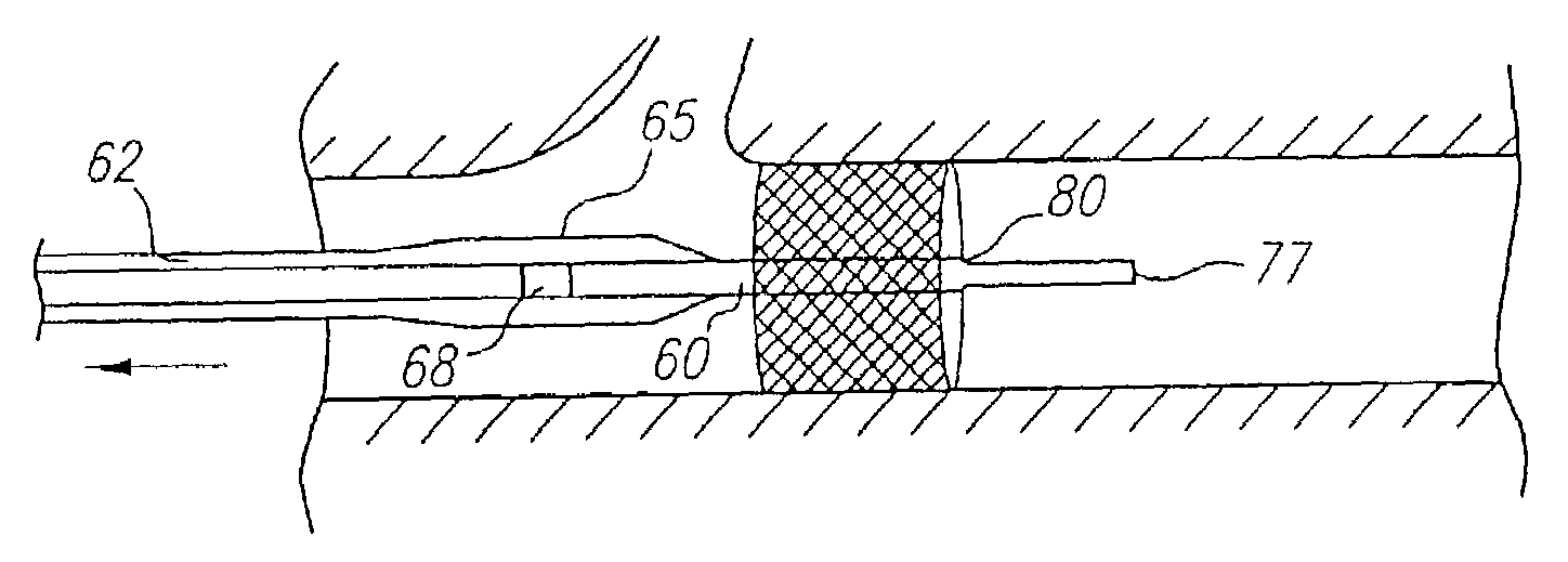
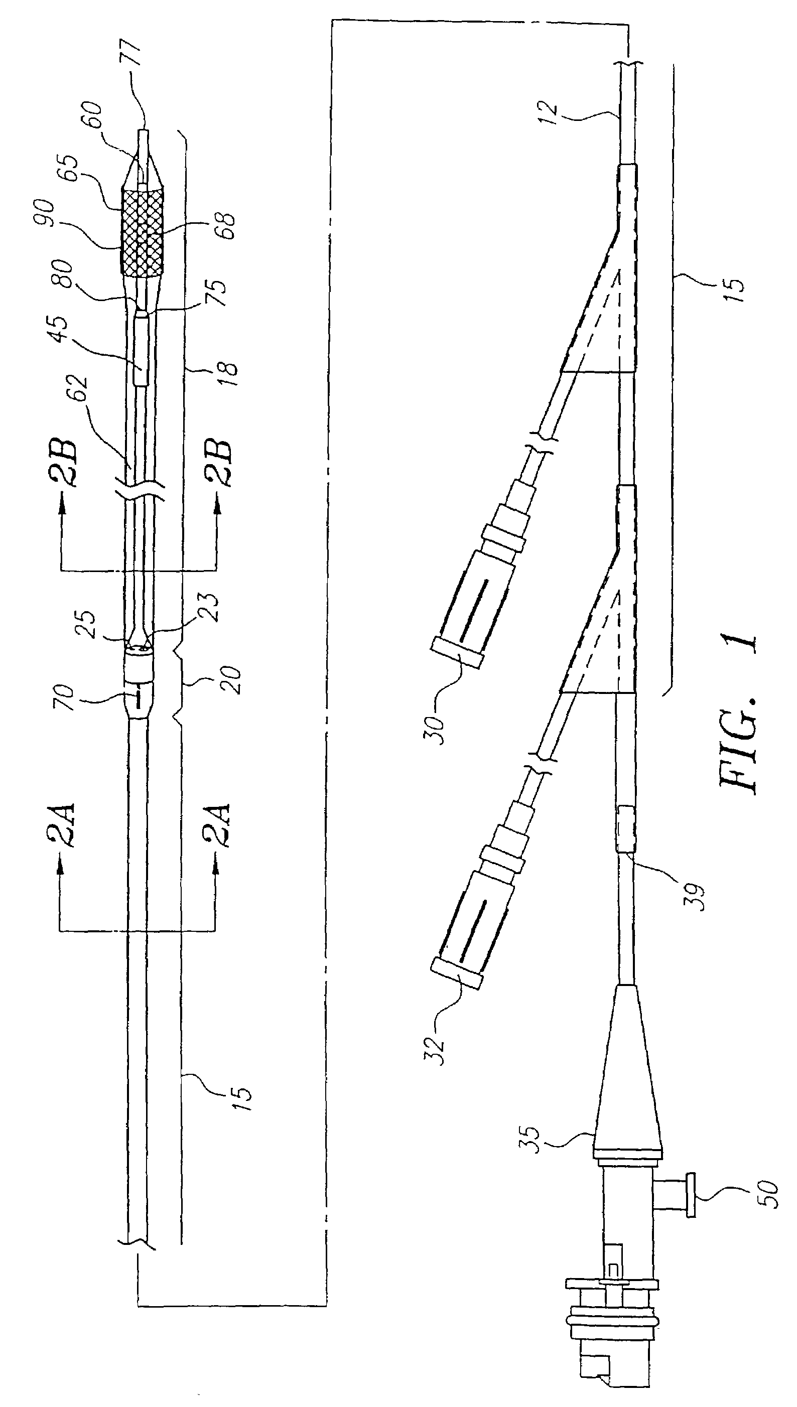
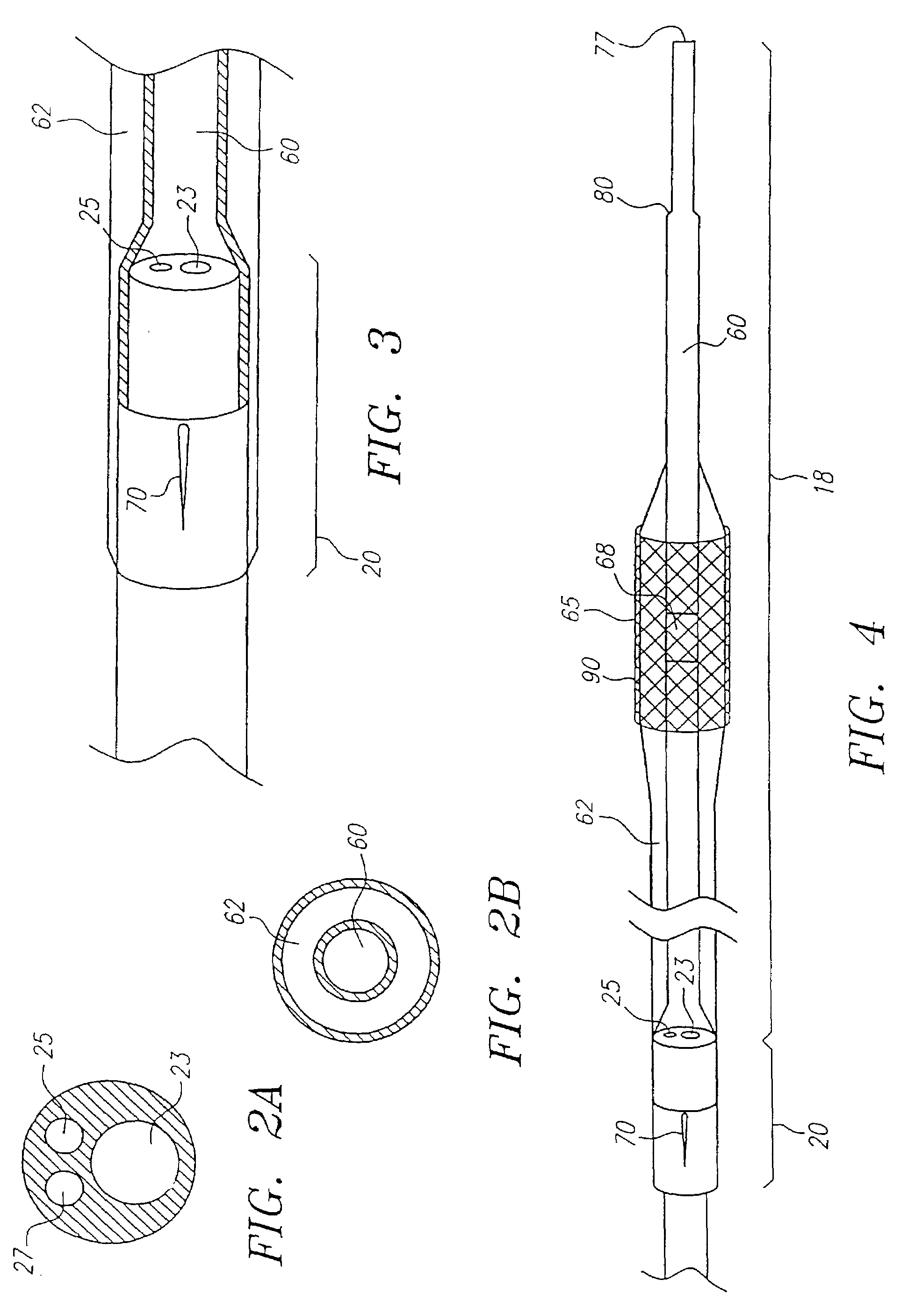
[0041]The prosthetic devices which are preferred for use with the catheters and methods described herein include stents, and particularly the Palmaz-Schatz stent which is available from Johnson & Johnson. Stents for use herein are disclosed in Palmaz, U.S. Pat. No. 4,733,665, and Cragg, U.S. Pat. No. 5,405,377, both of which are expressly incorporated herein by reference. Briefly, these stents include a tubular-shaped member having first and second ends and a wall surface disposed between the first and second ends, the wall surface being formed by a plurality of intersecting elongate members, at least some of the elongate members intersecting with one another intermediate the first and second ends of the tubular-shaped member; the tubular-shaped member having a first diameter which permits intraluminal delivery of the tubular-shaped member into a body passageway having a lumen; and the tubular-shaped member having a second, expanded diameter, upon the application from the interior o...


PUM


Abstract

A catheter system has a balloon angioplasty device disposed about a common lumen near its distal end. The balloon catheter is pre-fitted with a stent which is deployed when the balloon is inflated. The common lumen is in communication with multiple lumens within a proximal region of the catheter body to allow for positioning of the catheter over a movable guide wire and convenient delivery of imaging or interventional devices to a desired region of a body passageway being treated. The procedure for stent deployment optionally includes steps of imaging a lumen by ultrasound before and after stent deployment to identify the site at which a stent is needed, to confirm that the stent is being and has been deployed at a longitudinal position which does not overlap a branched segment of the body passageway, and to ensure that the stent has been radially opened to an optimum diameter.

Description

[0001]This application is a continuation application of U.S. Ser. No. 09 / 384,846 filed on Aug. 27, 1999, now abandoned which is a divisional of U.S. Ser. No. 08 / 880,947 filed on Jun. 23, 1997 which issued as U.S. Pat. No. 6,074,362, which is a divisional of U.S. Ser. No. 08 / 556,660 filed on Nov. 13, 1995 which issued as U.S. Pat. No. 5,749,848 on May 12, 1998.FIELD OF THE INVENTION[0002]The present invention relates generally to guided stent deployment using a catheter system for imaging and treatment of stenoses within a body passageway, including a patient's vascular system, and more particularly to a catheter system in which an angioplasty balloon can be used to deploy a stent device, said catheter system further including an imaging element for use within a region of a blood vessel so that placement and expansion of the stent can be observed.DESCRIPTION OF THE BACKGROUND ART[0003]Arteriosclerosis, also known as atherosclerosis, is a common human ailment arising from the depositi...

Claims


Application Information

Patent Timeline
Patent Type & Authority Patents(United States)
IPC IPC(8): A61F2/06A61F2/82A61F2/84
CPCA61F2/958Y10S623/902
Inventor JANG, YUE-TEHSALMON, STEPHEN M.WHITE, DAVID A.GARCIA, RIZZA A.
Owner BOSTON SCI SCIMED INC
Why Eureka
Try Eureka