Tracking device

a tracking device and tracking technology, applied in the direction of instruments, power management, high-level techniques, etc., can solve the problems of child wandering, child wandering, child wandering,

Inactive Publication Date: 2006-05-16
VITALTRAK TECH
View PDF7 Cites 155 Cited by
  • Summary
  • Abstract
  • Description
  • Claims
  • Application Information

AI Technical Summary

Benefits of technology

[0054]FIG. 2 is a block diagram of the parent unit 42 shown in FIG. 1. Signals from a ‘child’ unit are received by a pair of antennas 502 and 504. An antenna switch 506 switches based on a control signal 508 from a microprocessor unit 510. The microprocessor unit is advantageously selected to be a PIC 16L73B made by Microchip Technology, Inc. This is the presently preferred selection. Alternatives can be used with the appropriate design changes. Switching is controlled so that antennas 502 and 504 are alternately connected to a signal line 512 of antenna switch 506. Signal line 512 is coupled to a transceiver system 514 including a transceiver 516 so that the transceiver system can transmit signals to and receive signals from antennas 502 and 504 via antenna switch 506. Transceiver 516 is advantageously selected to be an RF2945 made by RF Micro Devices, Inc. This particular device merely represents the presently preferred choice. Alternatives can be used. For example, a transceiver with a built in synthesizer could be used. Such an arrangement would eliminate the need for a separate synthesizer.
[0058]However, it is more desirable to use only one receiver from the standpoint of minimizing cost and complexity. In order to use a single receiver, the two antennas must be multiplexed. This is accomplished by the use of antenna switch 506. Antenna switch 506 is essentially a single pole, two positions, RF switch. Switching between antennas is accomplished by applying a control signal to antenna switch 506 via signal line 508. When the control signal is in one state, the left antenna 502 is selected, and when the control signal switches to the opposite state, the right antenna 504 is selected. Thus, signals from antennas 502 and 504 can be alternately coupled to transceiver 516 in a time-multiplexed manner. Because the signals from antennas 502 and 504 are never present simultaneously, phase information from each of the antennas is temporarily stored and the stored phases are compared.

Problems solved by technology

Sometimes, when subjected to some adult activities such as shopping, a child may become curious or restless.
The child may have a tendency to wander.
In a matter of seconds, while the parent or guardian is distracted, a child can move quickly out of sight and become lost.
In most instances, the child is nearby but merely out of sight, however, in other cases, the child may be placed into danger.
In these cases, interference among the devices may be possible, which would render the devices inoperable and useless in locating lost children.

Method used


Image

  • Tracking device
  • Tracking device
  • Tracking device

Examples


Embodiment Construction

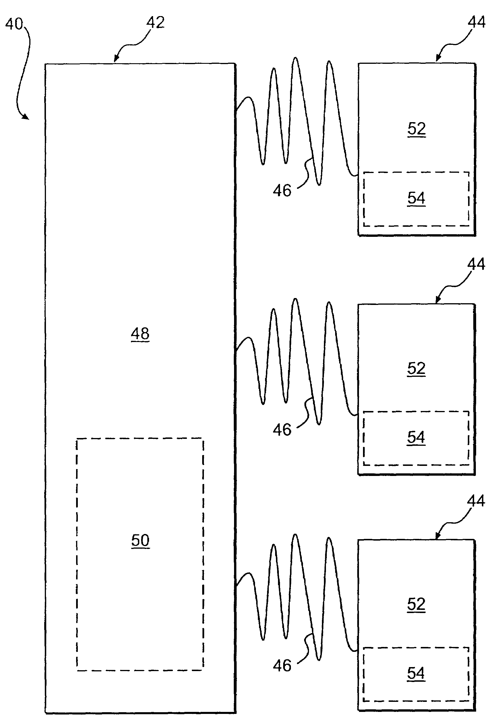
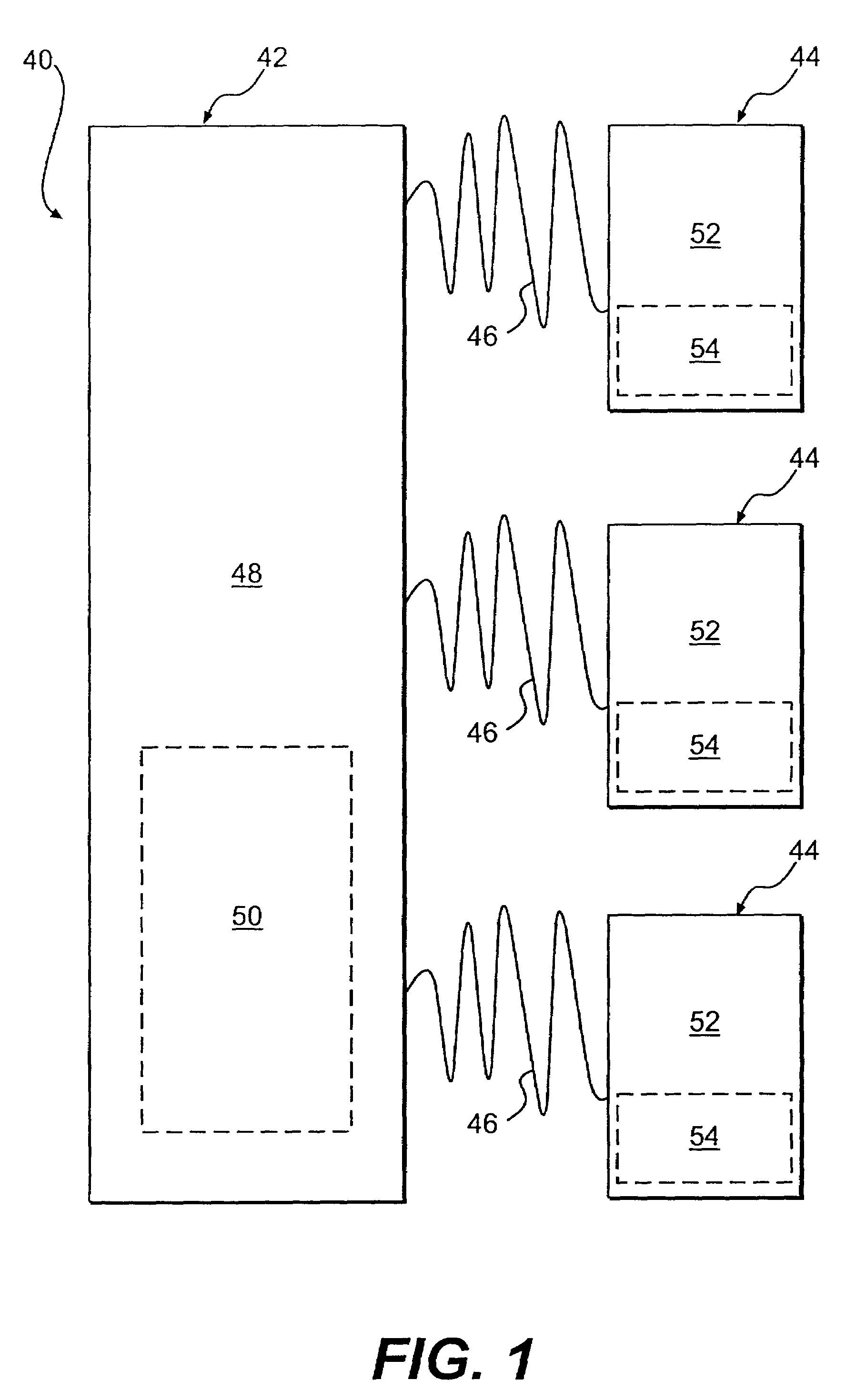
[0049]FIG. 1 is a block diagram showing the schematic arrangement of a monitoring and locating device constructed according to the inventions. The monitoring and locating device, generally indicated by reference numeral 40 includes a master control (hereafter referred to as parent unit), generally indicated by reference numeral 42, and one or more portable remote units (hereafter referred to as child units), generally indicated by reference numeral 44, in communication, e.g., radio frequency (RF), with the parent unit 42. The parent unit 42 acquires each of the plurality of child units 44 by assigning the child units 44 an individual identifier or ID code, generally indicated by 46. The parent unit 42 monitors and tracks each child unit 44 by transmitting and receiving signals including the ID code 46 to and from the child units 44, such that the parent unit 44 may be used to locate a selected child unit from the one or more child units 44. For example, the ID codes 46 may include a...


PUM


Abstract

A monitoring and locating device includes one or more remote child units and a parent unit in communication with each of the child units. The parent unit is adapted to assign and transmit an individual identifier to each child unit. The parent unit is constructed and arranged to continuously monitor each of the child units by transmitting and receiving signals to each of the child units using the individual identifiers assigned thereto. The monitoring and locating device may be used in a method for monitoring and tracking a living entity that includes acquiring the plurality of child units using the parent unit based at least in part on user input. Monitoring each of the plurality of child units individually with the parent unit. Tracking the location of each child unit with the parent unit and locating a selected child unit of the plurality of child units with the parent unit based upon the tracked location thereof.

Description

[0001]This application claims benefit of provitional application 60 / 275,519 filed Mar. 14, 2001.BACKGROUND[0002]1. Field of the Invention[0003]The present invention relates generally to tracking and locating objects and people. More specifically, the invention relates to a device and method for monitoring, tracking and locating an object or person, such as a child.[0004]2. General Background and Related Art[0005]Sometimes, when subjected to some adult activities such as shopping, a child may become curious or restless. The child may have a tendency to wander. In a matter of seconds, while the parent or guardian is distracted, a child can move quickly out of sight and become lost. In most instances, the child is nearby but merely out of sight, however, in other cases, the child may be placed into danger.[0006]To this end, monitoring and locating devices are used to quickly locate lost children. Some types of monitoring and locating devices, usually the wireless applications of the de...

Claims


Application Information

Patent Timeline
Patent Type & Authority Patents(United States)
IPC IPC(8): G08B23/00G08B21/02H04B1/16
CPCG08B21/0222G08B21/0227G08B21/023H04W52/0277G08B21/0263G08B21/0294G08B21/0247Y02D30/70
Inventor OJA, RAYMOND G.MOORE, ROGER A.HAMILTON, MILTON E.HREHA, MICHAEL
Owner VITALTRAK TECH
Why Eureka
Try Eureka