In-plane field type liquid crystal display device comprising liquid crystal molecules with more than two kinds of reorientation directions

a liquid crystal display device and in-plane field technology, applied in static indicating devices, instruments, non-linear optics, etc., can solve the problems of narrow isochromaticity range, inability to achieve the same viewing angle characteristics as self-, etc., and achieve the effect of greatly reducing the dependence on viewing angle of color tone chang

Inactive Publication Date: 2006-05-16
PANASONIC LIQUID CRYSTAL DISPLAY CO LTD +1
View PDF17 Cites 13 Cited by
  • Summary
  • Abstract
  • Description
  • Claims
  • Application Information

AI Technical Summary

Benefits of technology

[0015]That is, when liquid crystal molecules are twisted by rotation and viewing angle is tilted to the major-axis direction of the molecules, the birefringence anisotropy of the liquid crystal molecules more easily changes compared with the case of tilting the viewing angle to other directions, so that gradation level is more easily inverted and color tone more easily changes in the major-axis direction than in other directions.
[0018]The present invention has been made to solve the above mentioned problems of the prior art and its object is to provide an art for realizing wide viewing angle characteristics equal to those of a CRT and improving the image quality for an active-matrix liquid crystal display device using the in-plane field type.
[0047]According to the above means, shifts of color tones are offset each other and the dependency of color-tone on a viewing angle can greatly be reduced because the initial orientation angle φ LC is made different for neighboring picture elements or in one picture element so as to form two or more kinds of reorientation directions.
[0053]Therefore, by rotating liquid crystal molecules in two directions for each picture element or in one picture element, and by creating two reorientation states where the major-axis directions of the two states are nearly perpendicular to each other in displaying a white image or a half-tone image, color tones of the two states are offset each other and the viewing angle dependency of color tone change can greatly be reduced.

Problems solved by technology

However, the active-matrix liquid crystal display device using the in-plane field type cited above has a problem that viewing angle characteristics equal to those of a self-light-emitting display device such as a cathode ray tube (CRT) cannot be achieved because a homogeneous color tone cannot be realized and the viewing angle range of isochromaticity narrows when tilting a viewing angle to a certain direction.

Method used


Image

  • In-plane field type liquid crystal display device comprising liquid crystal molecules with more than two kinds of reorientation directions
  • In-plane field type liquid crystal display device comprising liquid crystal molecules with more than two kinds of reorientation directions
  • In-plane field type liquid crystal display device comprising liquid crystal molecules with more than two kinds of reorientation directions

Examples


embodiment 1

[0101]First, the in-plane field type active-matrix color liquid crystal display device constituted in accordance with embodiment 1 of the present invention is outlined below.

[0102]>

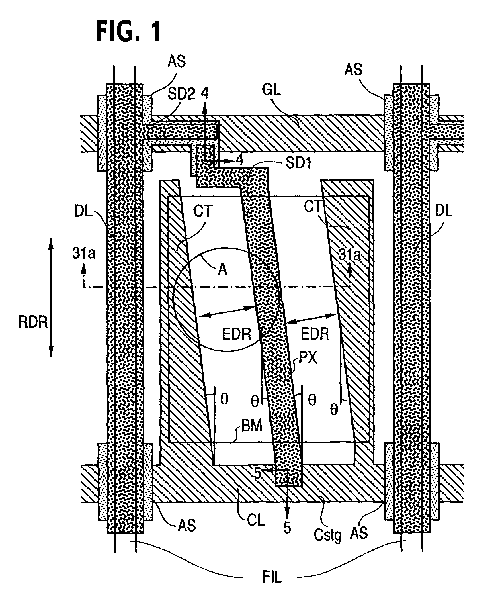
[0103]FIG. 1 is a top view showing one picture element and its neighborhood of the active-matrix color liquid crystal display device of embodiment 1 of an invention of the present invention.

[0104]Each picture element is arranged in a region (a region enclosed by four signal lines) where two adjacent scanning signal lines (gate signal lines or horizontal signal lines) (GL) and two adjacent video signal lines (drain signal lines or vertical signal lines) (DL) intersect.

[0105]Each picture element includes thin film transistor (TFT), storage capacitance (Cstg), a pixel electrode (PX), two counter electrodes (CT), and a counter voltage signal line (a common signal line) (CL).

[0106]In FIG. 1, a plurality of scanning signal lines (GL) and a plurality of counter voltage signal lines (CL) are arranged in the verti...

embodiment 2

[0299]FIG. 4 is a top view showing one picture element and its neighborhood of the active-matrix color liquid crystal display device of embodiment 2 of the present invention.

[0300]FIGS. 5A and 5B are illustrations showing the directions (EDR) of applied electric fields, the directions of polarized-light transmission axes (OD1 and OD2) of polarizing plates (POL1 and POL2), and driving directions of liquid crystal molecules (LC) in the liquid crystal display device of the embodiment 2 of the present invention. The structure of the embodiment 2 of the present invention is the same as that of embodiment 1 of the present invention except the shapes of a pixel electrode (PX) and two counter electrodes (CT).

[0301]In the case of the embodiment 2 of the present invention, as shown in FIG. 4, a pixel electrode (PX) forms an approximately triangular shape extending diagonally downward, two counter electrodes (CT) protruding upward from a counter voltage signal line (CL) form a comb tooth shape...

embodiment 3

[0307]FIG. 7 is a top view showing one picture element and its neighborhood of the active-matrix color liquid crystal display device of embodiment 3 of the present invention.

[0308]FIGS. 8A and 8B are illustrations showing the directions (EDR) of applied electric field, the directions of polarized-light transmission axes (OD1 and OD2) of polarizing plates (POL1 and POL2), and driving directions of liquid crystal molecules (LC).

[0309]The structure of the embodiment 3 of the present invention is the same as that of embodiment 1 of the present invention except the shapes of two pixel electrodes (PX) and three counter electrodes (CT).

[0310]In the case of the embodiment 3 of the present invention, as shown in FIG. 7, two pixel electrode (PX) are tilted inside an opening region of light shielding film (BM) of one picture element and formed into a V shape, three counter electrodes (CT) form a comb tooth shape protruding upward from a counter voltage signal line (CL), and the region between ...


PUM

PropertyMeasurementUnit
angleaaaaaaaaaa
angleaaaaaaaaaa
angleaaaaaaaaaa

Abstract

An active matrix liquid crystal display device having a pair of substrates, a liquid crystal layer, scanning lines and video signal lines provided in a matrix manner, at least one pixel electrode and at least one common electrode. The pixel electrode is bent so as to be inclined in first and second directions which are symmetrical relative to the alignment direction of the liquid crystal. The first direction of the pixel electrode is at a plus predetermined angle relative to the alignment direction, while the second direction of the pixel electrode is at a minus predetermined angle relative to the alignment direction.

Description

CROSS REFERENCE TO RELATED APPLICATION[0001]This is a continuation of U.S. application Ser. No. 10 / 237,756, filed Sep. 10, 2002, which is a continuation of U.S. application Ser. No. 09 / 841,100, filed Apr. 25, 2001, now U.S. Pat. No. 6,545,658, which is a continuation U.S. application Ser. No. 08 / 722,849, filed Sep. 26, 1996, now U.S. Pat. No. 6,266,116, the subject matter of which is incorporated by reference herein, this application being related to and copending with U.S. application Ser. Nos. 10 / 400,498, 10 / 400,637 and 10 / 400,668, each of which was filed Mar. 28, 2003 and is a continuation of U.S. application Ser. No. 10 / 237,756, filed Sep. 10, 2002 and U.S. application Ser. No. 10 / 400,498, filed Mar. 28, 2003, which is a continuation of U.S. application Ser. No. 09 / 841,100, filed Apr. 25, 2001, now U.S. Pat. No. 6,545,658.BACKGROUND OF THE INVENTION[0002](1) Field of the Invention[0003]The present invention relates to a liquid crystal display device and its manufacturing method,...

Claims


Application Information

Patent Timeline
Patent Type & Authority Patents(United States)
IPC IPC(8): G02F1/1343G02F1/1333
CPCG02F1/134363G02F1/133707G02F1/133528G02F1/133753G02F1/1362G02F1/137
Inventor OHTA, MASUYUKIYANAGAWA, KAZUHIKOOGAWA, KAZUHIROASHIZAWA, KEIICHIROYANAI, MASAHIROKONISHI, NOBUTAKEKONDO, KATSUMIOHE, MASAHITOARATANI, SUKEKAZUKLAUSMANN, HAGEN
Owner PANASONIC LIQUID CRYSTAL DISPLAY CO LTD
Why Eureka
Try Eureka