Bandwidth management apparatus and method, program therefor and recording medium with the program recorded thereon

a technology of bandwidth management and program recording, applied in frequency-division multiplex, data switching network, instruments, etc., can solve the problems of inability to achieve required packet routing, loss or missing, and achieve the effect of low computation complexity and ease in estimating the admissible bandwidth

Inactive Publication Date: 2006-05-16
NIPPON TELEGRAPH & TELEPHONE CORP
View PDF5 Cites 23 Cited by
  • Summary
  • Abstract
  • Description
  • Claims
  • Application Information

AI Technical Summary

Benefits of technology

[0007]It is therefore an object of the present invention to provide a bandwidth management apparatus and method that allow ease in estimating the admissible bandwidth for a new bandwidth reserv...

Problems solved by technology

Since the packet routing by SPF takes place irrespective of individual traffic, however, particular paths or links in the network m...

Method used


Image

  • Bandwidth management apparatus and method, program therefor and recording medium with the program recorded thereon
  • Bandwidth management apparatus and method, program therefor and recording medium with the program recorded thereon
  • Bandwidth management apparatus and method, program therefor and recording medium with the program recorded thereon

Examples


embodiment 1

[0070]In this embodiment, if no destination is specified in a new x-[Mb / s] bandwidth reservation of the EF or assured forwarding class for input traffic to the edge node ND4, for instance, the same x-[Mb / s] bandwidth is reserved, as depicted in FIG. 6, for the shortest paths P42, P42 and P43 to the edge nodes ND1, ND2 and ND3 which are each selectable as the destination. This is intended to facilitate the traffic management throughout the Diffserv network.

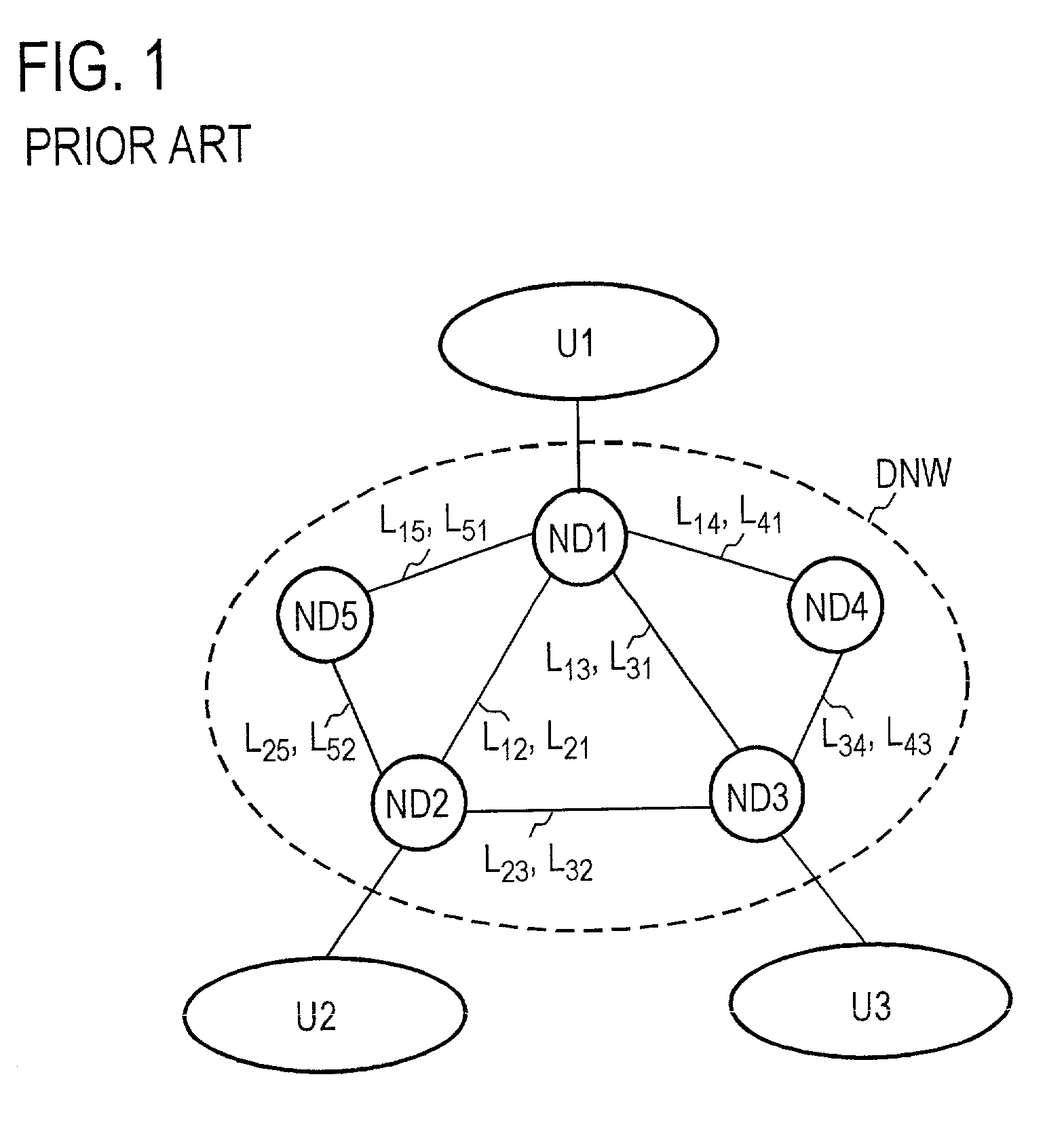
[0071]For example, when bandwidths x1, x2, x3 and x4 have already been reserved for input traffic to the edge nodes ND1, ND2, ND3 and ND4 as depicted in FIG. 7, the following method is used to seek a band y [Mb / s] that can be newly reserved for the input traffic to the edge node ND4. Let it be assumed, in this example, that two edge nodes are connected by two links separately provided in opposite directions. For example, the edge nodes ND1 and ND2 are connected by the link L12 from ND1 to ND2 and the link L21 from ND2 to ND1, and e...

embodiment 2

[0099]In the first embodiment described above, the bandwidth management apparatus 100 responds to the bandwidth reservation request RQ for the input traffic to the edge node NDj to reserve the requested bandwidth x in each of the shortest paths from the edge node NDj to all the other edge nodes each specified as the destination of the traffic. In this instance, however, since different paths (to the edge nodes ND2 and ND3, for instance) are formed which pass through the same link (for example, L12 in FIG. 8), the same bandwidth x is reserved in the same link a plurality of times as is evident from the description given above with reference to FIGS. 6 and 7—this is undesirable in terms of the link utilization efficiency. The second embodiment is intended to avoid such duplicate reservation of the same requested bandwidth in the same link.

[0100]FIG. 11 is a schematic showing of the requested bandwidth reservation processing according to this embodiment. Assume that the shortest paths ...


PUM


Abstract

Based on requested bandwidths received from all edge nodes and destination edge nodes, the total reservation of the bandwidths requested by respective edge nodes for each link is calculated, and the total value is subtracted from the maximum admissible bandwidth of the link to obtain the residual bandwidth, and it is decided whether a new requested bandwidth is less than the residual band of which link of the path to the destination edge node.

Description

BACKGROUND OF THE INVENTION[0001]The present invention relates to a bandwidth management method and apparatus for use in a connectionless IP (Internet Protocol) communication network or the like which is free from the necessity of setting a connection prior to the start of communication and, more particularly, a bandwidth management method and apparatus for a communication network which guarantees the minimum communication bandwidth.[0002]In a connectionless communication network like the IP communication network, there are no end-to-end paths predetermined. In other words, it is not predetermined over which path the input datagram packet is to be routed through the network. Upon input of the packet to one node in the network, the node router refers to its forwarding table and determines the link to which the packet is to be sent next in accordance with the destination address contained in the header of the packet.[0003]The forwarding table is determined by an SPF (Shortest Path Fir...

Claims


Application Information

Patent Timeline
IPC IPC(8): G06F15/16H04L12/54H04L47/724
CPCH04L12/5695H04L47/10H04L47/829H04L47/724H04L47/822H04L47/15H04L47/70
Inventor OISHI, TAKAHIROOMOTANI, MASAAKISHIOMOTO, KOHEI
Owner NIPPON TELEGRAPH & TELEPHONE CORP
Why Eureka
Try Eureka