Method for designing and fabricating multi-step tension prestressed girder

a multi-step tension, prestressing technology, applied in the direction of girders, bridges, building repairs, etc., can solve the problems of insufficient bending moment due to load increase, no remarkable developments in basic methods of prestressing, etc., to achieve the effect of increasing the tension in the steel wire, reducing the height of the girder, and improving the load bearing force of the girder

Inactive Publication Date: 2006-05-23
INTERCONSTEC
View PDF14 Cites 14 Cited by
  • Summary
  • Abstract
  • Description
  • Claims
  • Application Information

AI Technical Summary

Benefits of technology

[0015]To achieve the above object, a girder having a built-in steel wire which can be adjusted according to the present invention includes at least one steel wire installed in a lower flange of the girder in a lengthwise direction. Thus, by increasing the tension in the steel wire, a load bearing force of the girder can be improved.
[0016]According to one aspect of the present invention, there is provided a method for designing a multi-step tension prestressed girder, in which prestress is appropriately introduced with respect to a relationship between a load and stress for each step of construction, so that the height of a profile of the girder can be reduced.
[0017]According to another aspect of the present invention, there is provided a method for fabricating a multi-step tension prestressed girder, wherein prestress is appropriately introduced with respect to a relationship between a load and stress for each step of construction, so that the height of a profile of the girder can be reduced.

Problems solved by technology

However, there have been no remarkable developments in basic methods of introducing prestress to the member and the conventional design methods have still been used.
Also, since a tension process is performed only one time, great prestress, considering an overall loss of tension, needs to be introduced initially.
However, such a state is theoretical.
However, as the span increases, the bending moment due to the load increases in proportion to the square of the distance of the span.
Therefore, though the profile of the member is deformed to improve the efficiency of withstanding stress, the aforesaid basic problem cannot be solved and this fact has been a great disadvantage in designing a long-span bridge using a PSC I-type girder.

Method used


Image

  • Method for designing and fabricating multi-step tension prestressed girder
  • Method for designing and fabricating multi-step tension prestressed girder
  • Method for designing and fabricating multi-step tension prestressed girder

Examples


Embodiment Construction

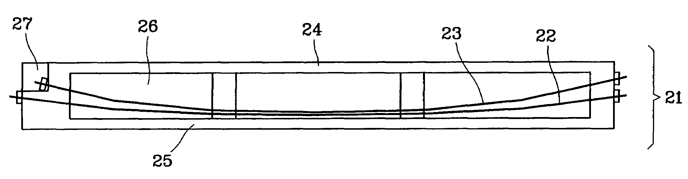
[0027]Referring to FIG. 3, a girder designed according to the present invention includes at least two steel wires. One of the steel wires is tightened when a girder is fabricated so that it can bear the self-weight thereof when the girder is installed on piers while the other can be tightened later when a slab is installed above the girder.

[0028]A girder 21 of the present invention, as shown in FIG. 3, includes an upper flange 24, a lower flange 25, and a body 26. At least two steel wires 22 and 23 are installed lengthwise throughout a lower end of the body 26 and the lower flange 25 of the girder 21.

[0029]Also, one steel wire 23 of the steel wires 22 and 23 is preferably installed inside the lower flange 25 in a lengthwise direction to be symmetric with respect to the center of the profile. In view of the profile of the girder 21, the upper flange 24 is installed horizontally at the upper portion of the body 26 and an upper plate of a bridge is installed on the upper flange 24. In ...


PUM


Abstract

In a method for designing a multi-step tension prestressed girder, prestress is appropriately introduced with respect to a relationship between a load and stress, for each step of construction, so that the height of a profile of the girder can be reduced. In a method for fabricating a multi-step tension prestressed girder, prestress is appropriately introduced with respect to a relationship between a load and stress, for each step of construction, so that the height of a profile of the girder can be reduced.

Description

BACKGROUND OF THE INVENTION[0001]1. Field of the Invention[0002]The present invention is related to a design of a girder for a bridge or for use in construction, and more particularly, to a method for designing and fabricating a multi-step tension prestressed girder to increase a load bearing force of a bridge, when necessary, by adjusting tension step by step during construction.[0003]2. Description of the Related Art[0004]FIG. 1 shows the arrangement of steel wires between girders according to a conventional design. Referring to the drawing, a prestressed concrete girder 11 includes an upper flange 13, a lower flange 14, and a body 15. A steel wire 12 is installed lengthwise in the girder 11 from end to end through the body 15, near the lower flange 14. In the conventional girder design, girders having various profiles is have been developed to be sturdier and longer in an effort to improve the efficiency of a member. However, there have been no remarkable developments in basic me...

Claims


Application Information

Patent Timeline
Patent Type & Authority Patents(United States)
IPC IPC(8): E04B1/20E04B1/22E01D1/00E01D2/00E01D2/02E01D21/00E01D101/24E01D101/26E01D101/28E04C3/26E04C5/08
CPCE01D2/00E01D2/02E04G21/12E04C3/26E01D21/00E01D2101/28E04C5/08
Inventor HAN, MAN-YOP
Owner INTERCONSTEC
Why Eureka
Try Eureka