Injection methods to reduce nitrogen oxides emission from gas turbines combustors

a gas turbine and nitrogen oxide technology, applied in the direction of machines/engines, mechanical equipment, separation processes, etc., can solve the problems of increasing the formation of carbon monoxide, reducing the combustion temperature, so as to reduce the residual nox, reduce the formation of thermal nitrogen oxides, and reduce the effect of high nitrogen oxide reduction

Inactive Publication Date: 2006-05-23
ZAUDERER BERT
View PDF7 Cites 31 Cited by
  • Summary
  • Abstract
  • Description
  • Claims
  • Application Information

AI Technical Summary

Benefits of technology

[0022]The invention discloses a process comprising three steps that alone or in combination reduce the concentration of nitrogen oxides, NOx, in the products of combustion from natural gas or liquid fuel in a gas turbine. The process is implemented in the turbine's combustion chambers. The invention is primarily aimed at certain types of gas turbines that have no or minimal NOx emission controls. All three steps effect these reductions by using air or hydraulic atomizing droplet injectors that generate droplets of varying size whose mean diameter depends on the specific method used to disperse said droplets throughout the three different zones in the combustion chamber of the turbines. The first step, applicable to liquid fuels, uses one or more injectors to disperse very fine fuel droplets to achieve rapid and complete combustion in a zone immediately downstream of the fuel injectors. The second step uses one or more injectors to disperse water droplets in a zone immediately downstream of the initial combustion zone, with the evaporation of said droplets lowering the gas temperature to a range that suppresses the formation of thermal nitrogen oxides. The third step uses one or more injectors to disperse aqueous droplets containing urea or ammonia to further reduce the residual NOx downstream of the water droplet injection zone. The design, placement, and operation of the injectors used by the three methods achieve high nitrogen oxide reductions.
[0023]In an alternate to step three, additional fuel is mixed with a nitrogen oxide reducing agent and it is injected in zone three to convert the combustion gases to slightly fuel rich conditions, which reduces NOx as does the NOx reducing reagent, ammonia or urea. The benefit of this combined alternate step three is that the urea or ammonia will be totally destroyed, thereby eliminating the possibility of ammonia corrosion on downstream turbine components. Final combustion occurs with mixing with compressor outlet air immediately downstream of zone three.

Problems solved by technology

However, increasingly stringent limitations on the emission of nitrogen oxides from older gas turbines with little or no nitrogen oxides, NOx, emission controls have resulted in their retirement or limited their use to power production emergencies with annual operating limits ranging from several 10's of hours to several 100's of hours.
However, in times of extended power shortages, such as has occurred in California in 2000 and 2001, government authorities have allowed these turbines to be placed into service for as much as several 1000 hours annually, provided the high NOx emissions are offset with lower emissions from other NOx producing industrial machinery, or by payment of an extremely high NOx emission fee.
While this waiver makes it economical to operate gas turbines with some NOx control, it is prohibitively expensive to operate turbines having no NOx control.
However, lowering the combustion temperature increased the formation of carbon monoxide, CO.
In the case of heavy residual fuels, which have substantial fuel bound nitrogen, water injection is to some extent counterproductive because the NOx yield from fuel bound nitrogen increases.
Lefebvre shows (FIG. 1120, p.485) that injecting the water with the combustion air is much less effective in reducing NOx compared to injecting directly into the primary combustion zone.
However, steam may be unsuitable for simple cycle, peaking turbines, which may not have access to high-pressure steam from a boiler.
Also, it has the same deficiency as water injection near the fuel inlet in that unburned hydrocarbons and carbon monoxide will increase.
In addition, it is more difficult to assure uniform mixing of the steam and combustion gas to yield uniform gas temperature reduction and reduce NOx.
Apparently this latter method cannot be combined with steam injection, presumably because staged combustion already lowers the gas temperature to the range where thermal NOx is mostly suppressed.
This procedure is very complex and costly.
Schorr also notes that the Selective Catalytic Reduction, SCR, process, which is placed at the turbine exhaust and can achieve the lowest NOx levels reported to date, namely 5 ppm, or less, is not suitable for simple cycle turbines because the exhaust temperatures are too high for the catalyst.
He also notes that even minute quantities of sulfur in the fuel can have very detrimental impact of the SCR system.
It is also to be noted that the SCR process is much too costly for peaking turbines that are used for short periods each year.
Older gas turbines were equipped with un-cooled metal turbine wheel blades that cannot withstand direct contact with the combustion gases whose temperatures are well in excess of 2000° F. Even modem turbines with cooled blades cannot operate with gas temperatures above 3000° F. Consequently, part of the compressor air is directed to regions downstream of the primary combustion zone to cool the combustion gases to temperatures compatible with turbine materials.
Furthermore, many of these peaking turbines use fuel oil, which also contains undesirable chemicals that require their periodic removal during the shutdown periods.
However, water or steam injection will not be effective with fuel bound NOx.

Method used


Image

  • Injection methods to reduce nitrogen oxides emission from gas turbines combustors
  • Injection methods to reduce nitrogen oxides emission from gas turbines combustors
  • Injection methods to reduce nitrogen oxides emission from gas turbines combustors

Examples


Embodiment Construction

Tests in a Small Gas Turbine

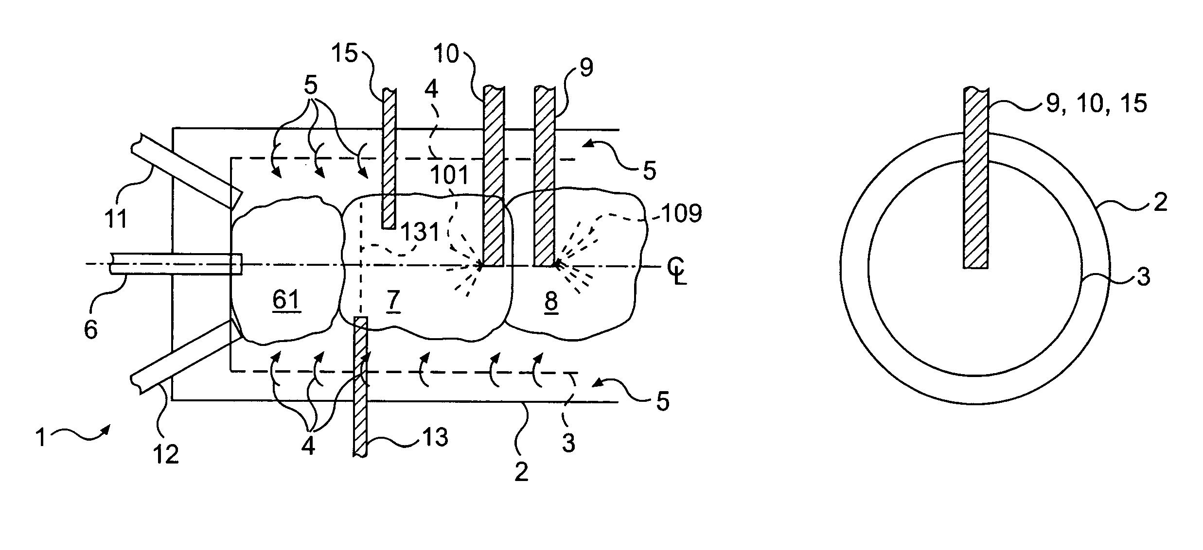
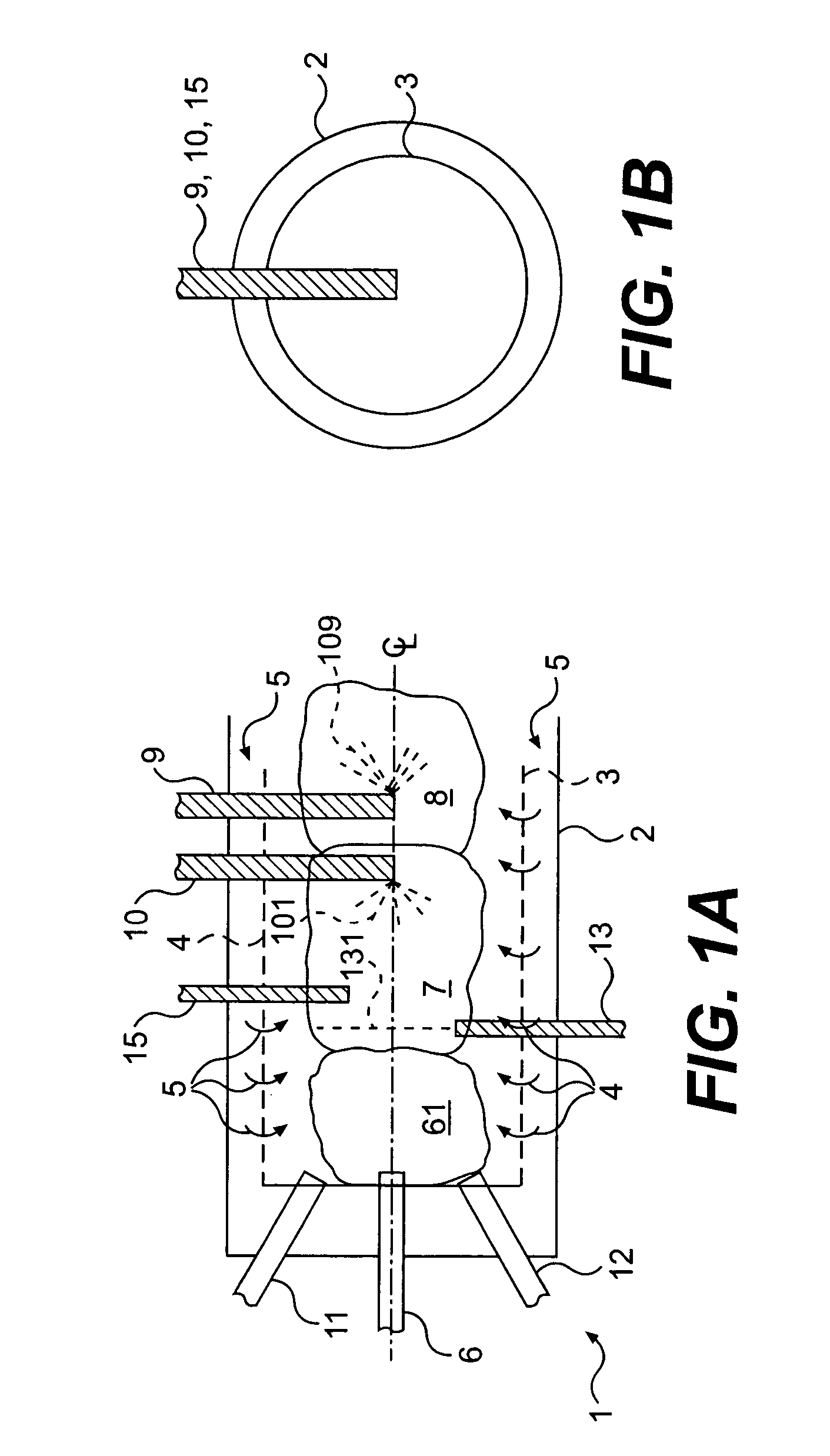
[0070]The NOx reducing potential of the present invention was evaluated in a series of about four-dozen short duration tests in June through August 2001 using a 120 hp gas turbine of the late 1950's. It had originally been used to start Naval jet aircraft. Solar Aircraft manufactured this Model No: GTC85-6 turbine. It was designed to drive a 70 kW 400 hz generator, a 12 kW 6-hz generator, and to provide compressed air drawn from a bleed valve at the compressor outlet. An earlier design of this engine is described by Jennings (loc. cit. Sec. 8–15). For the present tests, the unit was operated without the generators, and with the compressor bleed air providing a partial load on the turbine. The key component for the present NOx tests is the combustion chamber. It consisted of a perforated high alloy cylinder, 4 inches in diameter and 12 inches long. One end of the chamber terminates in a dome, at whose top has a hydraulic fuel nozzle. The other end of the c...


PUM


Abstract

A process having three steps utilized individually or in combination to reduce nitrogen oxides, NOx, emissions from gas turbines. One or more injectors disperse very fine fuel droplets to achieve rapid and complete combustion in zone one immediately downstream of the fuel injectors. The second step uses one or more injectors inserted into the combustor to disperse water droplets throughout zone two, immediately downstream of zone one, to lower the gas temperature and suppress formation of thermal NOx,. The third step uses one or more injectors to disperse aqueous droplets containing a dissolved NOx reducing agent throughout zone three, immediately downstream of zone two, and whose gas temperature favors the reduction of NOx. Alternatively, the dissolved NOx reducing agent can be mixed with a liquid fuel to convert zone three into slightly fuel rich conditions, enabling nitrogen oxide reduction at higher gas temperatures.

Description

CROSS REFERENCE TO RELATED APPLICATIONS[0001]This application claims priority to U.S. provisional application Ser. No. 60 / 433,609, filed on Dec. 16, 2002, and U.S. provisional application No. 60 / 430,090, filed on Dec. 2, 2002, all of which are incorporated herein by reference in their entirety.BACKGROUND OF THE INVENTION[0002]1. Field of the Invention[0003]This invention discloses methods whereby the emissions of nitrogen oxides, NOx, from existing combustion gas turbines that have little or no NOx reduction controls can be reduced.[0004]2. Description of Prior Art[0005]Electricity demand varies hourly, daily and seasonally with peak demand occurring during mid-day, during the summer air conditioning season. Simple cycle gas turbines are especially suited to meet this peaking demand due to their relative simplicity and rapid startup capability, and they have been used for decades for this purpose. However, increasingly stringent limitations on the emission of nitrogen oxides from ol...

Claims


Application Information

Patent Timeline
Patent Type & Authority Patents(United States)
IPC IPC(8): F02C3/30B01D53/56
CPCB01D53/56
Inventor ZAUDERER, BERT
Owner ZAUDERER BERT
Why Eureka
Try Eureka