
Animal stall soil agitator

a soil agitator and animal stall technology, applied in the field of animal stall soil agitator, can solve the problems of high cost of sand added, unfavorable conditions for cattle, and possible unhealthy environment,

Inactive Publication Date: 2006-05-23
BRADE GENE M
View PDF12 Cites 13 Cited by
  • Summary
  • Abstract
  • Description
  • Claims
  • Application Information

AI Technical Summary

Problems solved by technology

Cattle lying in a stall tends to create a depression and compact the sand.
Mud and wet sand in the depressions sticks to cattle laying in the depressions creating an uncomfortable condition and possibly an unhealthy environment for cattle.
Frozen wet sand is cold, hard, and uncomfortable for cattle.
The sand that is added is expensive.
The frequent addition of sand to keep stalls relatively dry and clean results in a substantial material handling and disposal tasks that are expensive.
It is also difficult to store clean replacement sand in an unfrozen state during winter months in northern areas.

Method used


Image

  • Animal stall soil agitator
  • Animal stall soil agitator
  • Animal stall soil agitator

Examples


Embodiment Construction

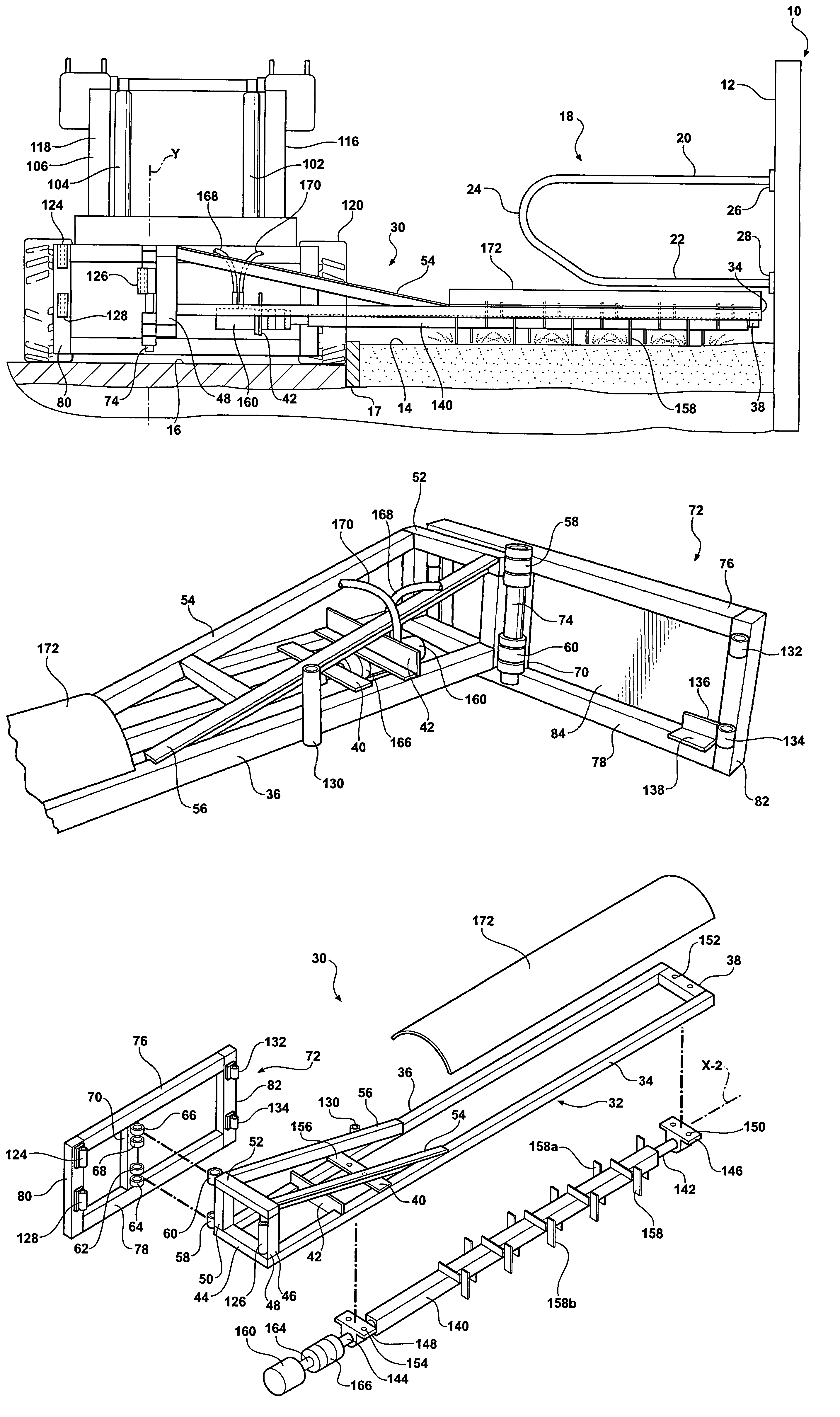
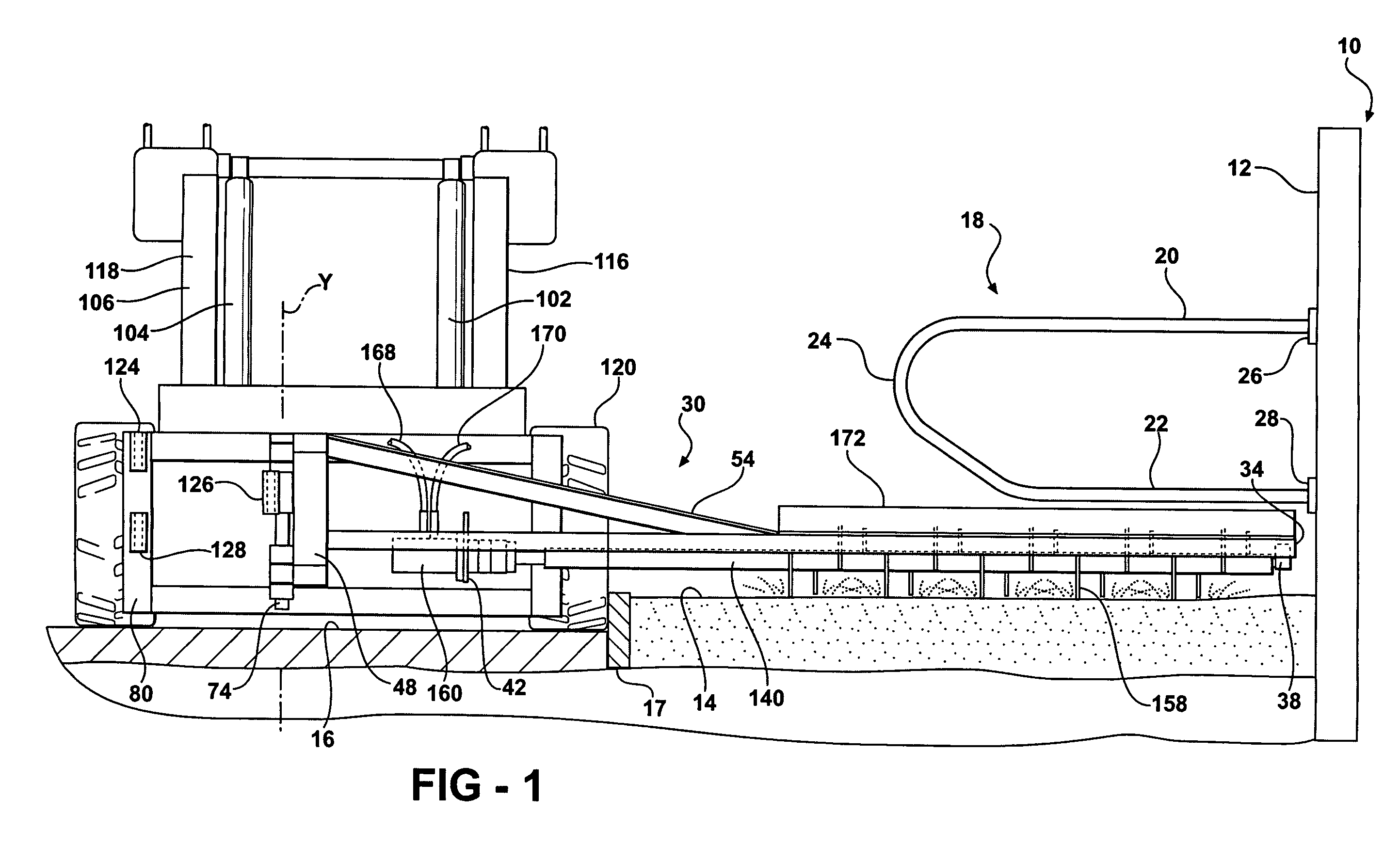
[0014]A livestock barn 10, a portion of which is shown in FIG. 1, includes a wall 12, a floor with a stall area 14, an alley 16 and a curb 17 separating the stall area 14 from the alley 16. The stall area 14 in large livestock barns 10 extend for some distance along the wall 12. Stall dividers 18 divide the stall area 14 into a number of individual stalls each of which is sufficiently large to permit an animal to lie down or to stand. The stall dividers 18 as shown are a generally unshaped tube with an upper horizontal arm 20, a lower horizontal arm 22, and a bight portion 24 connecting the upper and lower arms together. Free ends of the upper arm 20 and the lower arm 22 are anchored to the wall 12 by flanges 26 and 28 and mechanical fasteners (not shown). The lower arm 22 is elevated above the curb 17.

[0015]The alley 16 is generally a concrete slab with an upper surface that is generally horizontal. The floor of the stall area 14 is sand. The sand is preferably several inches deep....


PUM


Abstract

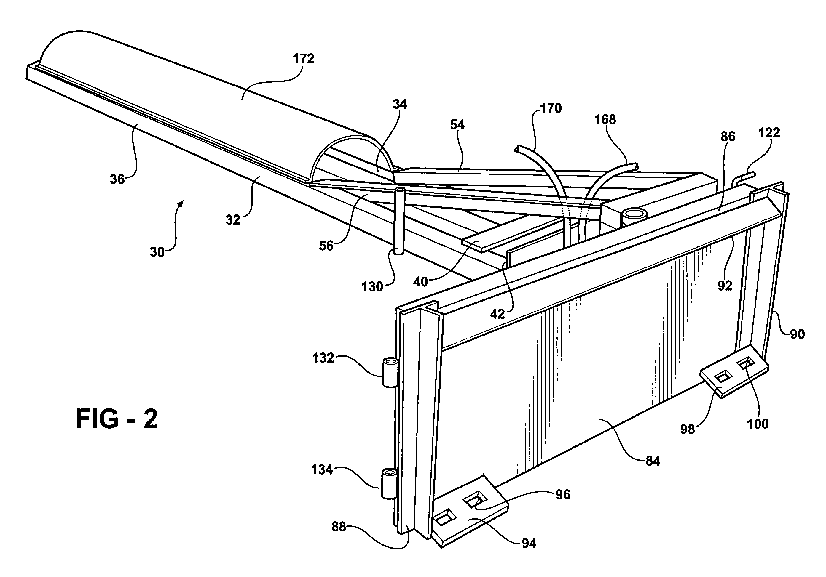
The animal stall soil agitator includes a mounting plate assembly pivotally attached to a tractor loader boom for pivotal movement about a transverse horizontal loader boom axis. An elongated frame assembly has an inboard frame end attached to the mounting plate assembly and outboard frame end that extends laterally to one side of the tractor loader boom. An elongated bar is journaled on the elongated frame assembly. A plurality of flat soil agitator bars are fixed to the elongated bar. The flat soil agitator bars are oriented to minimize lateral movement of agitated soil. A reversible hydraulic motor is connected to a hydraulic system of the tractor and rotates the elongated bar in a selected direction. The elongated frame assembly is pivotable about a vertical axis relative to the mounting plate.

Description

TECHNICAL FIELD[0001]The soil of a barn stall floor is agitated by a hydraulically driven rotor, with a plurality of rigid tines, journaled on a frame mounted on a tractor mounted loader boom for rotation about a horizontal axis, extending laterally out to one side of the tractor, and wherein the frame is pivotable about the horizontal axis.BACKGROUND OF THE INVENTION[0002]Cattle are often housed in confinement barns during the cold winter months. They may also be housed in confinement barns during hot summer months. Mild cows produce more milk if they are protected from very cold weather as well as from very hot weather. Cattle that are grown for their meat gain weight faster if they are protected from very cold weather as well as very hot weather. In a confinement facility cattle can also be protected from files and other insects. Cattle in a typical confinement facilities are provided access to water and to a balanced ration. Each animal in the facility has a stall. There is norm...

Claims


Application Information

Patent Timeline
IPC IPC(8): A01K31/04A01D7/02
CPCA01K1/01A01K31/04A01K1/0128
Inventor BRADE, GENE M.
Owner BRADE GENE M
Learn More