Mud saver valve

a technology of mud retaining valve and pin, which is applied in the direction of sealing/packing, transportation and packaging, and well accessories, etc., can solve the problems of limiting the longevity of the pin and therefore the longevity of the valve, and the inability to include the mud retaining valve with a two-part body

Inactive Publication Date: 2006-05-23
MUDSAVER
View PDF8 Cites 5 Cited by
  • Summary
  • Abstract
  • Description
  • Claims
  • Application Information

AI Technical Summary

Problems solved by technology

Thus, on offshore rigs, where the height of the derrick or mast is usually limited, it may be impossible to include mud retaining type valve with a two-part body.
An additional disadvantage inherent in mud retaining valves with two-part bodies is that the pin of the lower body member replaces the pin of the kelly saver sub and is therefore subject to tremendous wear.
This wear limits the longevity of the pin and therefore the longevity of the valve.
However, this solution is not entirely satisfactory because it adds still more length to the string.
Neither of these valves is entirely satisfactory.
The frangib...

Method used


Image

  • Mud saver valve
  • Mud saver valve
  • Mud saver valve

Examples


Embodiment Construction

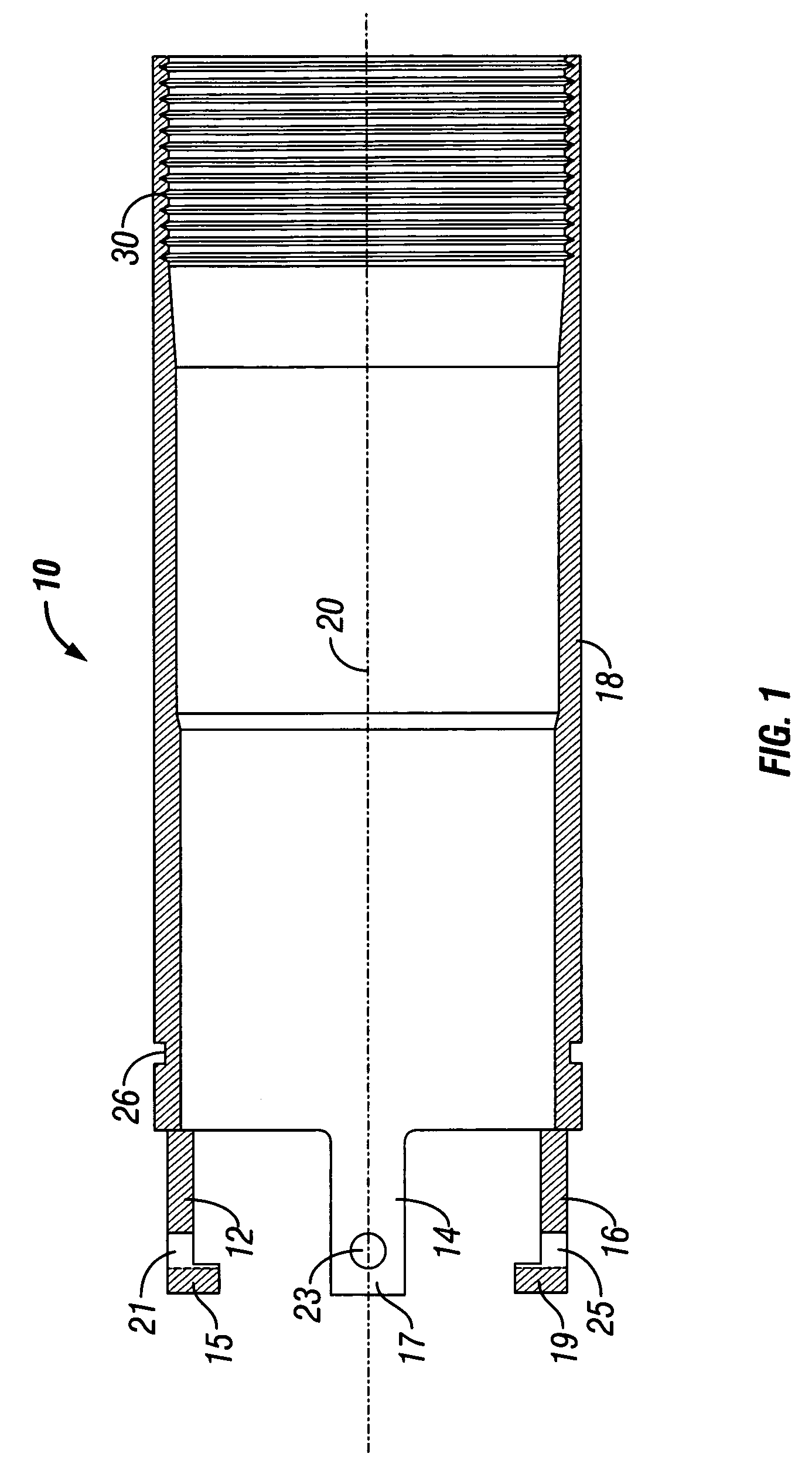
[0025]Referring now specifically to FIG. 1 of the drawing, there is illustrated a cylinder 10 having a first end with three extensions 12, 14 and 16 which run parallel to the sidewall 18 of the cylinder 10. The three extensions, 12, 14 and 16, are equally spaced around the perimeter of the first end of the cylinder 10. Each of the extensions has an end portion 15, 17 and 19, respectively, which are pointed in towards the longitudinal axis 20 of the cylinder 10. Each of the extensions 15, 17 and 19 also has a throughhole 21, 23 and 25, respectively which will be used to house a set screw as will be explained hereinafter with respect to the cap illustrated in FIGS. 8A and 8B.

[0026]Near the first end of the cylinder 10, right before the beginning of the extensions 12, 14 and 16, a groove 26 goes around the side wall 18 and is sized to receive an o-ring (not illustrated). At the second end of the cylinder 10, there is an internally threaded portion 30 which is threaded to accept the ext...


PUM


Abstract

A three-part sub-assembly comprising a wire line retrievable spear. The spear having two fluid chambers. A diverter valve having a truncated, inverted cone valve seat is preferably threaded into the interior of the spear. A diverter valve stem, having back-to-back cones is located within the interior of the spear/diverter valve combination, with one of the cones having a linear extension which prevents the first cone from completely seating against the valve seat within the interior of the spear. The spear/diverter valve assembly and a spring-loaded piston is placed within the interior of the cylinder and utilizes an adjustable ring within the interior of the cylinder as an adjustment for varying mud weights.

Description

BACKGROUND OF THE INVENTION[0001](A) Field of the Invention[0002]This invention relates to apparatus for preventing the loss of drilling mud when the kelly is disconnected from the drill pipe.[0003](B) Description of the Prior Art[0004]In the drilling of oil and gas wells, it is common practice to insert in the drilling string between the kelly and the drill pipe a valve to retain mud in the kelly when the drill string is broken. The advantages of using such a valve are well known and include saved mud cost, decreased chances of pollution, and increased safety to rig personnel.[0005]Typical valves of the mud retaining type are illustrated in the following patents:[0006]PatenteeU.S. Pat. No.Taylor3,331,385Garrett3,698,411Litchfield, et al3,738,436Williamson3,965,980Liljestrand3,967,679[0007]All of the above listed patents include a downwardly opening spring loaded poppet type valve enclosed in a body having at least two parts. These two extra pieces in the drill string replace a sing...

Claims


Application Information

Patent Timeline
IPC IPC(8): E21B21/10F16K51/00E21BE21B17/18
CPCE21B21/106Y10T137/6154
Inventor PARKER, WILLIAM B.
Owner MUDSAVER
Why Eureka
Try Eureka