Fluid control apparatus

a control apparatus and fluid technology, applied in the direction of braking components, operating means/releasing devices of valves, brake systems, etc., can solve the problems of affecting the operation the lip portion might be subject to compressive deformation, etc., to inhibit the reaction force, and reduce the cost and size of the fluid control apparatus.

Inactive Publication Date: 2006-05-23
ADVICS CO LTD
View PDF9 Cites 4 Cited by
  • Summary
  • Abstract
  • Description
  • Claims
  • Application Information

AI Technical Summary

Benefits of technology

[0005]In light of the above described problems, it is an object of the present invention to reduce a cost and a size of a fluid control apparatus while inhibiting reaction force of an elastic member that presses a coil portion to a cover from becoming excessively large.
[0006]According to an aspect of the present invention, a rate of change of reaction force with respect to an amount of deformation in a bending deformation range of an elastic member is less than a case where the elastic member is subject to compressive deformation. Therefore, even in the case where the amount of deformation of the elastic member increases due to dimensional variation of a component part, the reaction force of the elastic member pressing the coil portion to the cover does not become excessively large. Accordingly, it is possible to reduce a cost and a size of the fluid control apparatus.
[0007]According to a preferred form of the aspect of the present invention, a lip portion in a free state inclines toward a center line of the elastic member. If the lip portion in the free state is in parallel with the center line of the elastic member, the lip portion might be subject to compressive deformation when the elastic member is assembled. However, according to the present invention, by disposing the lip portion such that it inclines toward the center line of the elastic member in the free state, the lip portion can be reliably deformed by bending when the elastic member is assembled.

Problems solved by technology

If the lip portion in the free state is in parallel with the center line of the elastic member, the lip portion might be subject to compressive deformation when the elastic member is assembled.

Method used


Image

  • Fluid control apparatus
  • Fluid control apparatus
  • Fluid control apparatus

Examples


first embodiment

(First Embodiment)

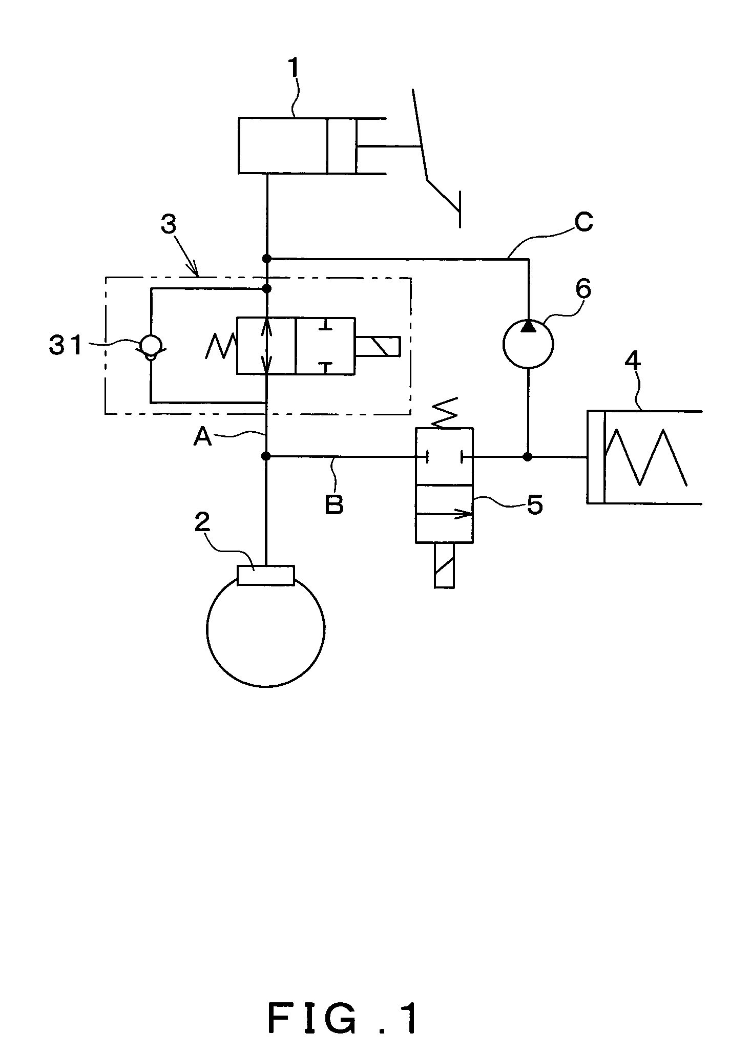
[0019]FIG. 1 shows a brake conduit configuration of a brake apparatus including an ABS actuator as a fluid control apparatus according to a first embodiment of the present invention.

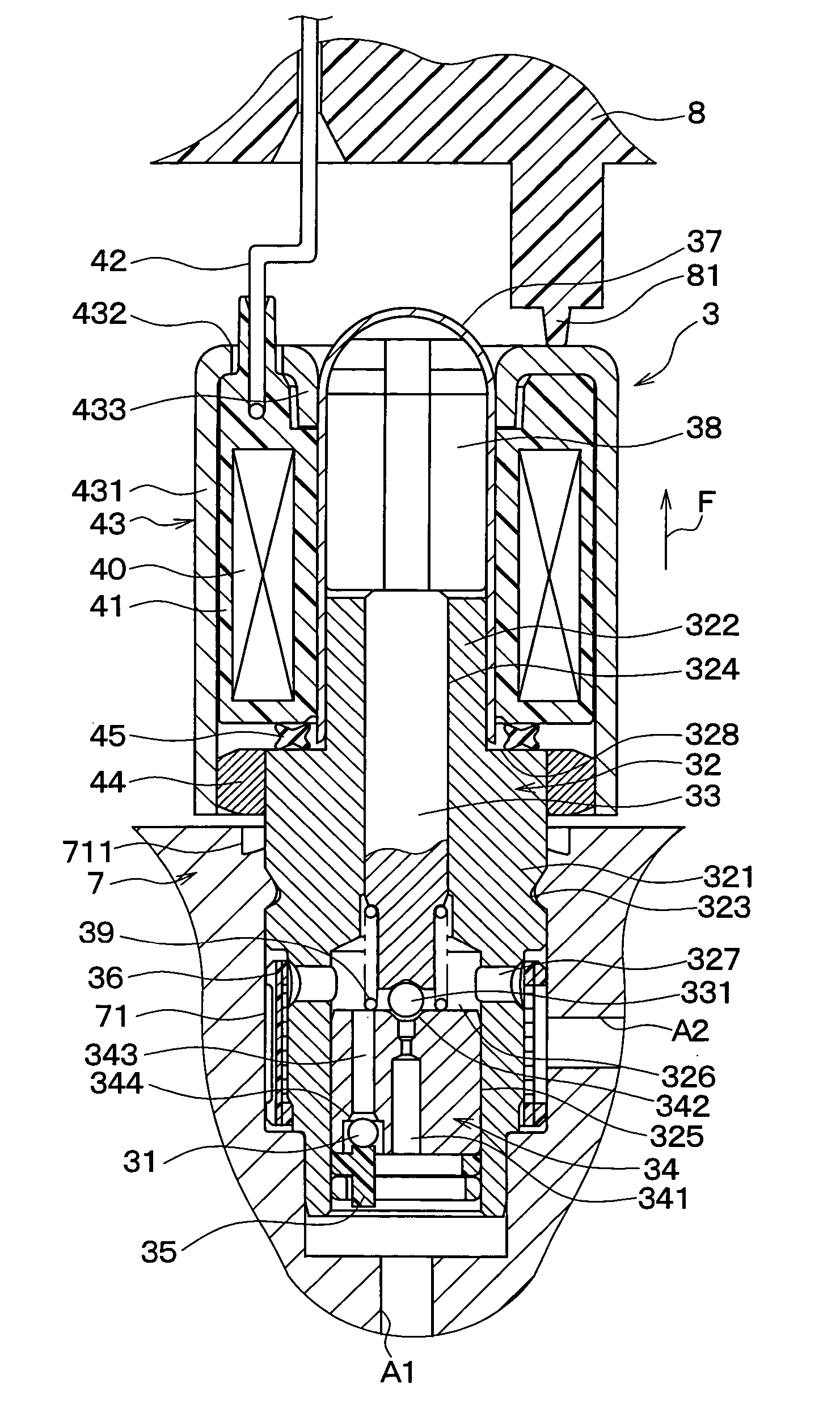
[0020]As shown in FIG. 1, a master cylinder 1 is connected to a wheel cylinder 2 through a brake conduit A. The brake conduit A allows brake fluid to flow from a side of the master cylinder 1 to a side of the wheel cylinder 2 through the brake conduit A. A pressure increase control valve 3 is provided in the brake conduit A for controlling communicated and closed states of the brake conduit A. Note that the pressure increase control valve 3 includes a check valve 31 which permits the brake fluid to flow only from the side of the wheel cylinder 2 to the side of the master cylinder 1. The pressure increase control valve 3 corresponds to a solenoid valve according to the present invention, and a detailed explanation thereof will be described later.

[0021]A portion of the brake conduit A on ...

second embodiment

(Second Embodiment)

[0058]In the second embodiment, the structure of the elastic member 45 of the first embodiment has been changed. FIG. 6 shows a structure of an elastic member 46 according to the second embodiment. FIG. 6 shows a cross section perpendicular to the circumferential direction of the elastic member 46. A solid line in FIG. 6 shows a shape of the elastic member 46 in the free state, and a dotted line in FIG. 6 shows a state where the elastic member 46 is assembled between the spool 41 and the guide 32 (see FIG. 3).

[0059]In FIG. 6, the elastic member 46 is formed of rubber into a ring-like shape, including two lip portions 461 and 462 that can be deformed by bending and a protruding portion 463 that is deformed by bending or deformed by compression. Specifically, the elastic member 46 has an inner peripheral lip portion 461 located on the inner peripheral side in the radial direction of the elastic member 46 and on one end side in the direction of the center line E; an ...

third embodiment

(Third Embodiment)

[0063]In the third embodiment, the structure of the elastic member 45 in the first embodiment has been changed. FIG. 7 shows a structure of an elastic member 47 according to the third embodiment. FIG. 7 shows a cross section perpendicular to the circumferential direction of the elastic member 47. A solid line in FIG. 7 shows a shape of the elastic member 47 in the free state, and a dotted line in FIG. 7 shows a state where the elastic member 47 is assembled between the spool 41 and the guide 32 (see FIG. 3).

[0064]In FIG. 7, the elastic member 47, formed of rubber into a ring-like shape, has a lip portion 471 which can be bent. The lip portion 471 in the free state inclines toward to the center line E, as can be seen from the cross sectional view perpendicular to the circumferential direction of the elastic member 47 (as shown by the solid line). More specifically, the lip portion 471 expands to the outer peripheral side in the radial direction from one end side to ...


PUM


Abstract

An elastic member made of rubber which urges a coil portion toward a cover is formed into a shape such that the elastic member can be deformed by bending. A rate of change in reaction force of the elastic member with respect to an amount of deformation in a bending deformation region is less than a case where the elastic member is subject to compressive deformation. Therefore, even in the case where the amount of deformation of the elastic member increases due to dimensional variation of a component part, the reaction force of the elastic member does not become excessively large.

Description

CROSS REFERENCE TO RELATED APPLICATION[0001]This application is based upon and claims the benefit of Japanese Patent Application No. 2003-180935 filed on Jun. 25, 2003, the content of which are incorporated herein by reference.FIELD OF THE INVENTION[0002]The present invention relates to a fluid control apparatus which opens and closes a fluid passage using a solenoid valve. For example, the present invention is preferably applied to an ABS actuator of an anti-lock brake system (ABS) in a vehicle for avoiding a locking of wheels by increasing and decreasing a brake fluid pressure.BACKGROUND OF THE INVENTION[0003]In a conventional ABS actuator, a fluid passage formed in a housing is opened and closed by a solenoid valve. Further, a coil portion of a solenoid valve is sandwiched between the housing and the cover, and the coil portion is pressed to a cover by an elastic member disposed between the coil portion and the housing (for example, as disclosed in Japanese Patent Laid-Open Appli...

Claims


Application Information

Patent Timeline
Patent Type & Authority Patents(United States)
IPC IPC(8): F16K31/06B60T8/34B60T8/36
CPCB60T8/3675B60T8/363
Inventor SHIBATA, TAKAYUKI
Owner ADVICS CO LTD
Why Eureka
Try Eureka