Drill measurement stops

a technology for measuring stops and drills, which is applied in the direction of twist drills, teeth capping, wood boring tools, etc., can solve the problems of increasing the stress of patients and/or operators, cycling is neither as convenient nor as useful, and it is difficult for operators to know precisely when a given depth has been reached

Inactive Publication Date: 2006-05-23
IDMS
View PDF30 Cites 77 Cited by
  • Summary
  • Abstract
  • Description
  • Claims
  • Application Information

AI Technical Summary

Benefits of technology

[0006]It is an object of the present invention is to provide a device that wil...

Problems solved by technology

In the mix of water, saliva and sometimes blood present in the mouth, the location of the implant site itself (often in or towards the rear of the mouth), and the generally high speed of rotation of the drill bit (several hundred or more revolutions per minute), even under the best of circumstances it is difficult for the operator to know precisely when a given...

Method used


Image

  • Drill measurement stops
  • Drill measurement stops
  • Drill measurement stops

Examples


Embodiment Construction

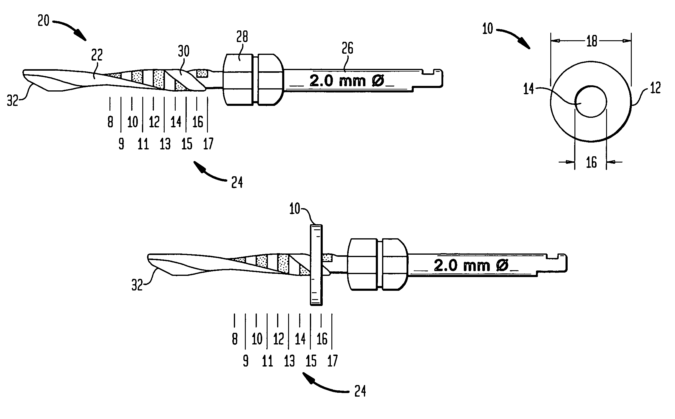
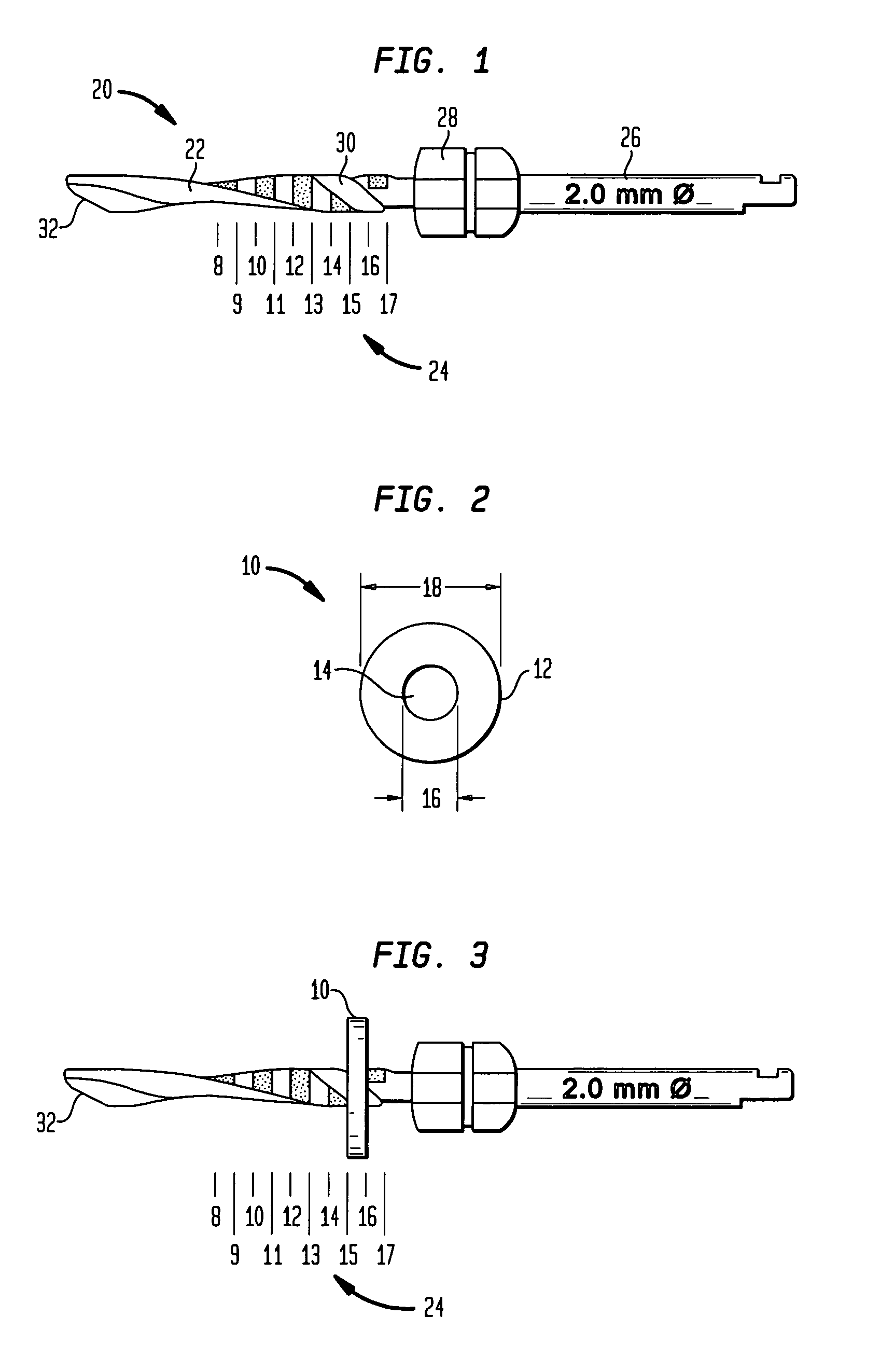
[0020]The present invention comprises a system of implant drill measurement stops 10 (also referred to herein as drill stops or depth stops) for attachment onto a drill bit 20 (FIG. 1). The drill stops decisively mark the depth measurement of the implant drill. An embodiment of the present invention is a drill stop 10 that has a body 12 with an opening 14 therein, an inner diameter 16 and outer diameter 18 (FIG. 2), the inner diameter being sized such that when the drill stop 10 is mounted on a drill bit, it provides a snug fit thereon. This facilitates the visualization of the depth of the osteotomy site while the drill is in operation in the field to reach the desired depth as marked with the stop 10. An embodiment of the present invention employs drill stops 10 that are color coded to indicate the range of drill bit diameters on which a particular drill stop can be used, enabling the user (also referred to herein as either operator or practitioner) to determine rapidly which stop...


PUM

PropertyMeasurementUnit
Sizeaaaaaaaaaa
Depthaaaaaaaaaa

Abstract

A depth stop for use with a drill bit comprises a tubular body having an opening therethrough. Used with a drill bit whose bit portion includes a cutting end, and a shank portion, the depth stop is frictionally positionable on the bit portion at a specified point from the cutting end, thereby indicating a specified depth. Depth stops are manufactured in different colors, each color corresponding to a specified range of drill bits that the depth stops will fit. The depth stops, manufactured from a sterilizable material, are intended for single use. The depth stop can be used with a drill bit and drill extender, where one or more depth stops provide multiple visual points of reference for the operator. The depth stops can be quickly mounted onto most any manufacturer's drill bits.

Description

CROSS-REFERENCE TO RELATED APPLICATION[0001]This application claims the benefit of U.S. Provisional Patent Application Ser. No. 60 / 483,787, filed 30 Jun. 2003, the contents of which are hereby incorporated by reference.FIELD OF THE INVENTION[0002]The present invention is a device for use in dental and medical procedures involving drilling. A particular embodiment is a depth measurement stop which is attached onto a drill bit, indicating to the drill operator that the drill has reached a specified depth.BACKGROUND OF THE INVENTION[0003]In the field of performing dental osteotomies for the placement of an implant to replace a tooth, it is necessary to prepare the site to receive the implant therein. This is generally done by means of a handpiece and drill bit, drilling into the existing bone to both a specified depth and a specified diameter before inserting the implant into the site.[0004]Some of the drill bits currently used for this procedure contain markings thereon to indicate th...

Claims


Application Information

Patent Timeline
IPC IPC(8): B23B51/00B23B51/02A61B17/16A61B19/00A61C5/02A61C8/00B23B49/00
CPCA61B17/1617A61C8/0089B23B49/005A61B2019/304A61C5/025Y10T408/03Y10T408/21Y10T408/957Y10T408/8925Y10T408/99Y10T408/907A61B2090/034A61C5/44
Inventor ABRAMS, STEVEN
Owner IDMS
Why Eureka
Try Eureka