
Device for applying thin layers of a powder or pulverulent material and corresponding method

a technology of pulverizing material and thin layer, applied in the field of devices, can solve the problems of inability to produce homogeneous layers, inability to meet industry requirements, and high preparation costs, and achieve the effect of simple, effective and convenient application

Inactive Publication Date: 2006-05-23
PHENIX SYST
View PDF11 Cites 58 Cited by
  • Summary
  • Abstract
  • Description
  • Claims
  • Application Information

AI Technical Summary

Benefits of technology

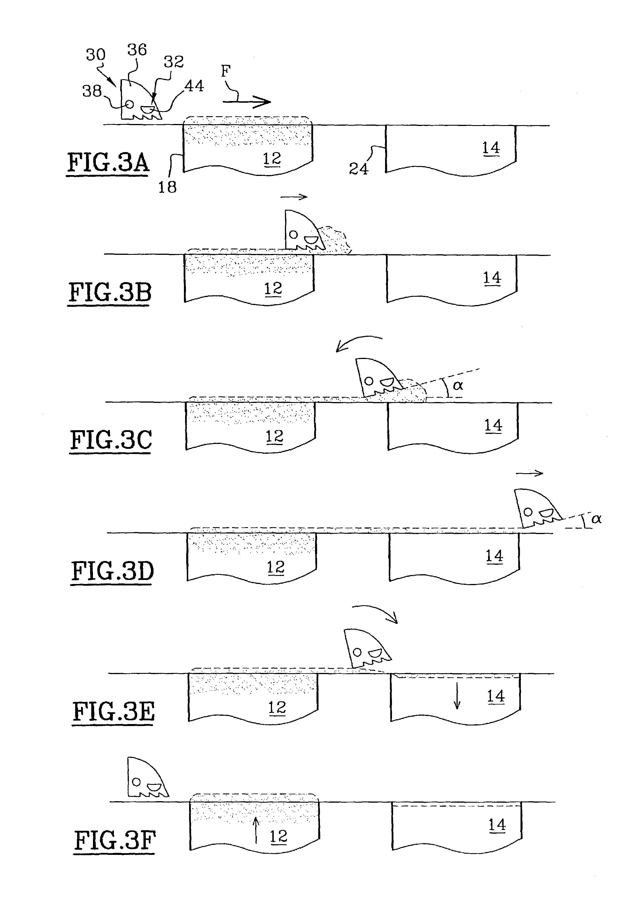
"The present invention provides a device for applying a layer of powder on a support surface. The device includes a screed with a movable shoe that can be inclined to take two positions. The shoe has a working surface with indentations that are triangular / rectangular in shape. The number of passages is determined based on the thickness of the layer and the granulometry of the powder. The device is simple and effective, and can be used on any machine. It is designed to swallow powders and can be easily mounted on existing machines."

Problems solved by technology

Such a preparation is costly and above all leads to unacceptable requirements for industry.
When the powders used are of the flour type, which is to say they swell, it becomes very difficult or even impossible to produce homogeneous layers.
In the case of swelling powders, when the layers are less than 100 μm, the screed totally moves the powder, zonewise, which creates impermissible defects to produce quality finished pieces by rapid prototyping.
Such a problem arises in the use of rapid prototyping but it generally is present when it is desired to lay down thin layers of swelling powders.

Method used


Image

  • Device for applying thin layers of a powder or pulverulent material and corresponding method
  • Device for applying thin layers of a powder or pulverulent material and corresponding method
  • Device for applying thin layers of a powder or pulverulent material and corresponding method

Examples


Embodiment Construction

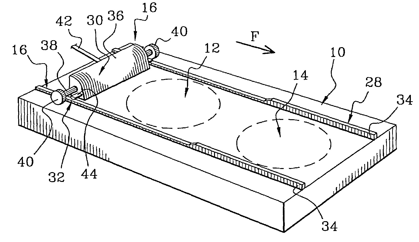
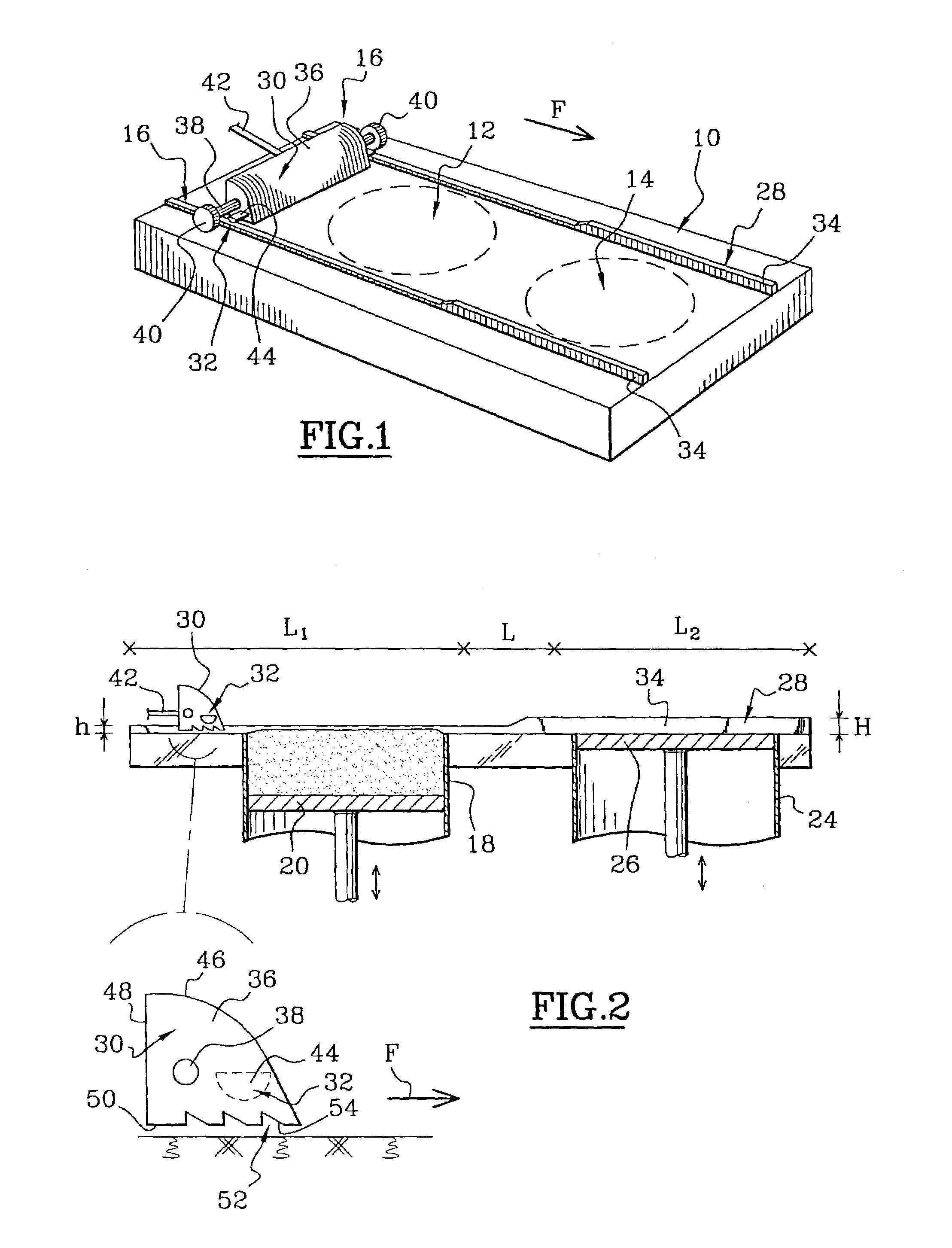
[0025]In FIG. 1, there is shown an installation which includes a device according to the present invention. This installation comprises a frame 10, means 12 for storage and supply of powder, means 14 for supporting thin layers and means 16 for screeding and applying a thin layer.

[0026]The storage means 12 comprise a well 18 containing the powder and provided with an internal piston 20, movable particularly in translation, which permits raising the upper level 22 of the powder relative to the frame, with very great precision.

[0027]The support means 14 for the thin layers of this installation, given by way of example, also comprise a well 24 permitting retracting a piston 26, movable vertically in translation in said well. The movements must also be very precise.

[0028]The screed means 16, movable in translation on guide means 28, comprise a screed 30 and follower means 32.

[0029]The guide means 28 are comprised by two rails 34 which have a first height h over a length L1 and a height H...


PUM

PropertyMeasurementUnit
heightaaaaaaaaaa
heightaaaaaaaaaa
thickaaaaaaaaaa

Abstract

A device for applying a thin layer of a powder on a support means (14) includes a device (12) for storing the powder, a screed (30) that includes a shoe (36) with a working surface, as well as a device (28) for guiding in translation in a direction of movement F. The shoe (36) is rotatable and includes a device (32, 34) for inclining the to take at least two positions, the first in which the working surface is parallel to the support (14) for the layers to take up a predetermined volume of powder and a second in which this working surface is inclined at an angle α relative to the support.

Description

BACKGROUND OF THE INVENTION[0001]The present invention relates to a device for applying thin layers of powder or pulverulent material, particularly for applying successive layers in machines for a rapid prototyping.[0002]The invention also relates to a process for laying down a layer with this device.[0003]There is known from the patent application PCT FR 99 / 00357 a process for rapid prototyping by laser sintering, which permits obtaining ceramic pieces of complex shapes from a three-dimensional image, by sintering superposed layers of powder with the help of a laser.[0004]Such a process requires the performance of steps of which one consists in spreading in the form of a thin layer the powder or mixture of powders and compacting this powder to increase its density.[0005]The thickness of such layers is of the order of several tens to several hundreds of microns.[0006]The means for forming the layers described above comprise a screed which permits transferring the powder contained in...

Claims


Application Information

Patent Timeline
Patent Type & Authority Patents(United States)
IPC IPC(8): B29C31/06B05D1/12B05C11/02B05C19/00B05C19/06B29C41/12B29C67/00
CPCB05C11/02B05C19/00B29C41/12B29K2105/251B29C67/0051Y02P10/25B22F12/67
Inventor GAILLARD, JEAN-MARIEHORY, ARNAUD
Owner PHENIX SYST
Learn More