Device for fixation of spinous processes

a technology for fixing devices and spinous processes, applied in the field of spine surgery, can solve problems such as unnecessary equipment and procedures

Active Publication Date: 2006-05-23
WARSAW ORTHOPEDIC INC
View PDF27 Cites 652 Cited by
  • Summary
  • Abstract
  • Description
  • Claims
  • Application Information

AI Technical Summary

Benefits of technology

[0007]Described briefly, according to a typical embodiment of the present invention, a fixation device for use in association with ALIF procedures includes a couple of spaced plates having integral spikes on facing surfaces thereof for pressing into spinal processes of adjacent vertebrae. One of the plates has a socket which captures one end of a post which is received through an aperture in the other plate. The socket mounting is arranged to enable the post to pivot therein for at least two degrees of freedom to a limited extent enabling angulation between the two plates so as to accommodate the different thicknesses and orientations of the spinal processes on adjacent vertebrae. The reception of the post in the second plate enables adjustment of spacing between the plates to accommodate effective installation of the assembly on the spinal processes by a compression instrument, and permanent reliable maintenance of that spacing following removal of the compression instrument. The cross-sectional configuration of the post and a receiver aperture in the plate inhibits rotation of the plate relative to the post about the post axis.

Problems solved by technology

With several systems, the use of the pedicles requires screws or other anchorage devices that occupy significant space and involve muscle dissection and associated work time for implantation.
We believe that such elaborate apparatus and procedures are unnecessary in many instances.

Method used


Image

  • Device for fixation of spinous processes
  • Device for fixation of spinous processes
  • Device for fixation of spinous processes

Examples


Embodiment Construction

[0019]For the purposes of promoting an understanding of the principles of the invention, reference will now be made to the embodiment illustrated in the drawings and specific language will be used to describe the same. It will nevertheless be understood that no limitation of the scope of the invention is thereby intended, such alterations and further modifications in the illustrated device, and such further applications of the principles of the invention as illustrated therein being contemplated as would normally occur to one skilled in the art to which the invention relates.

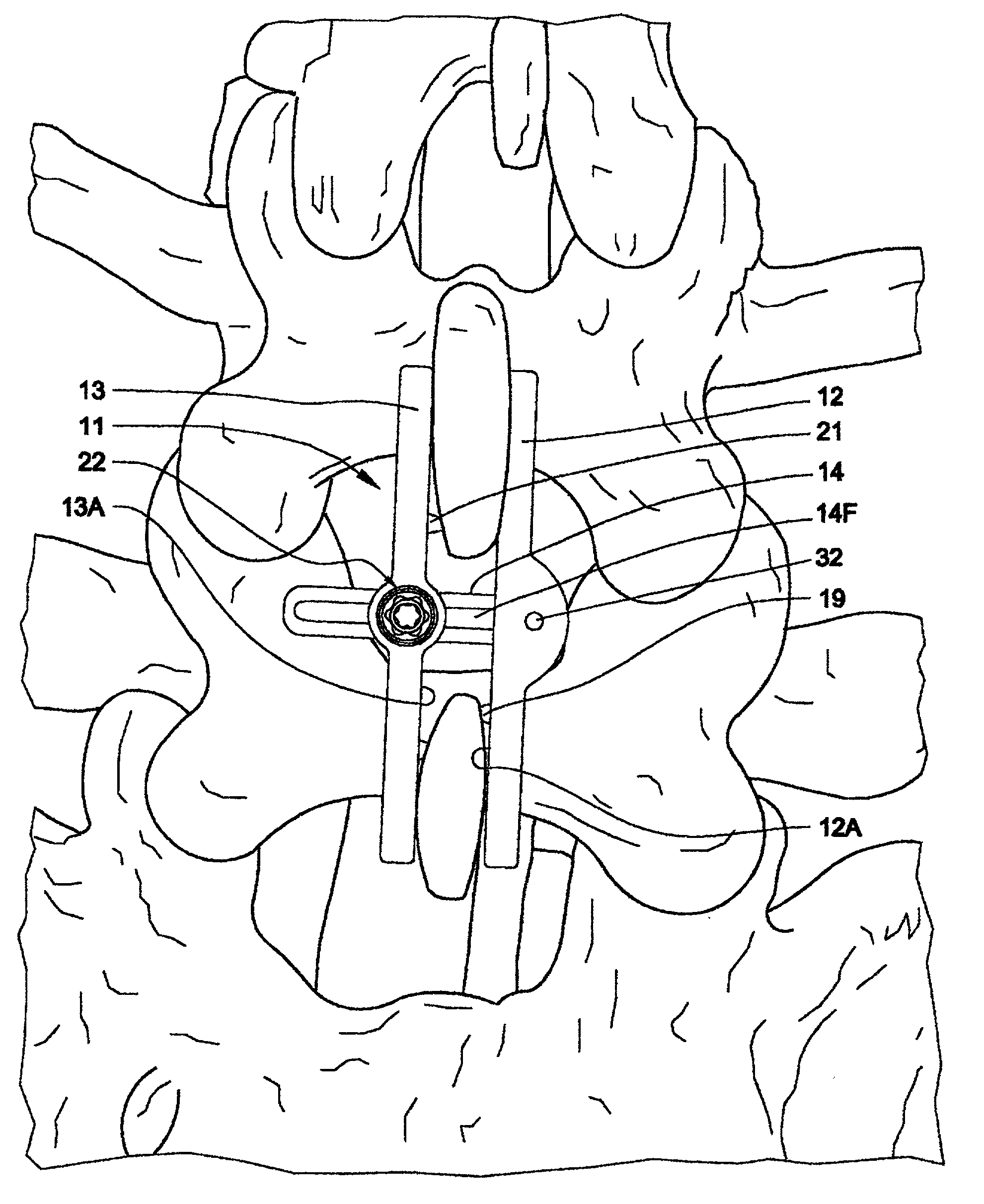
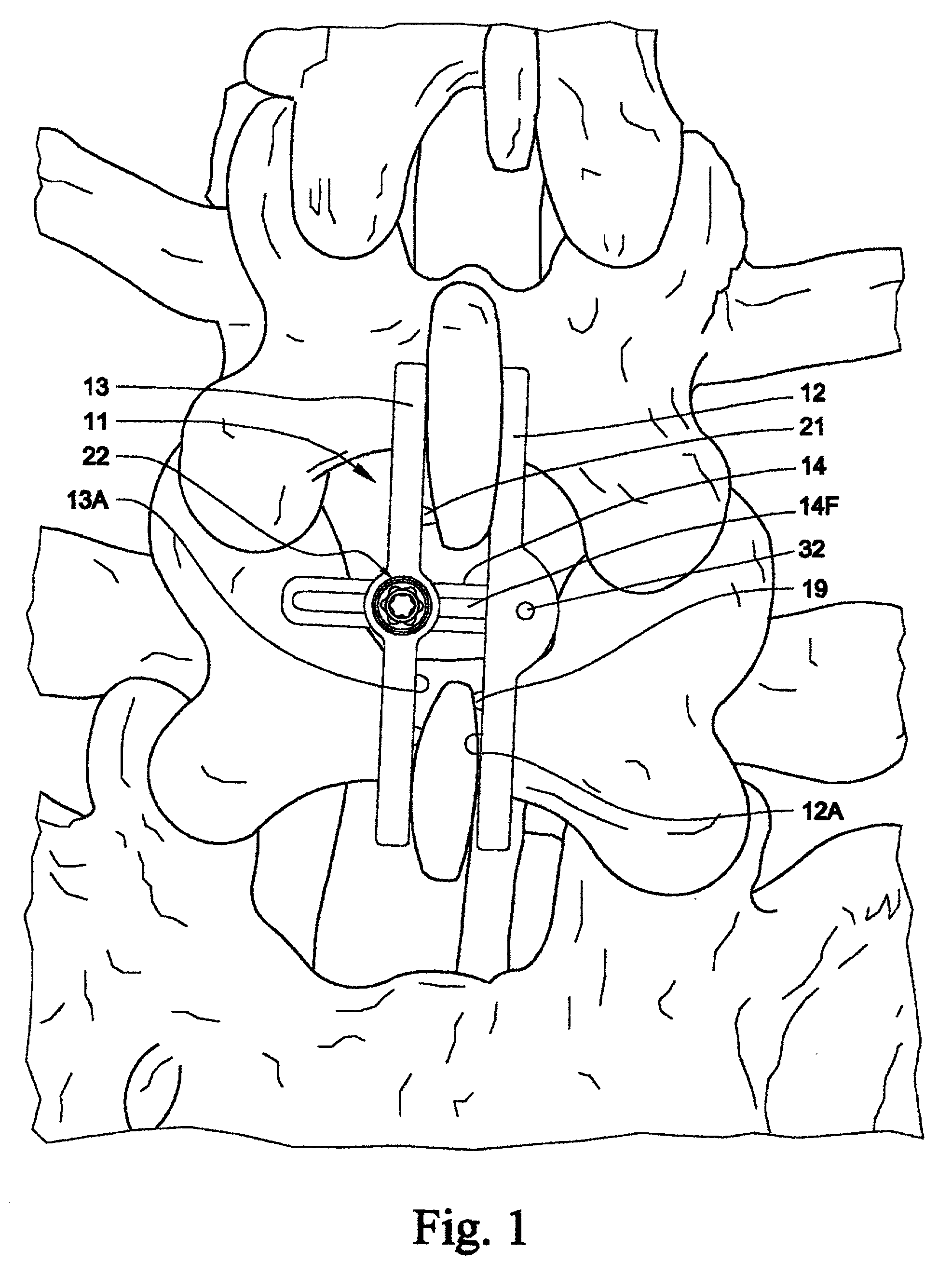
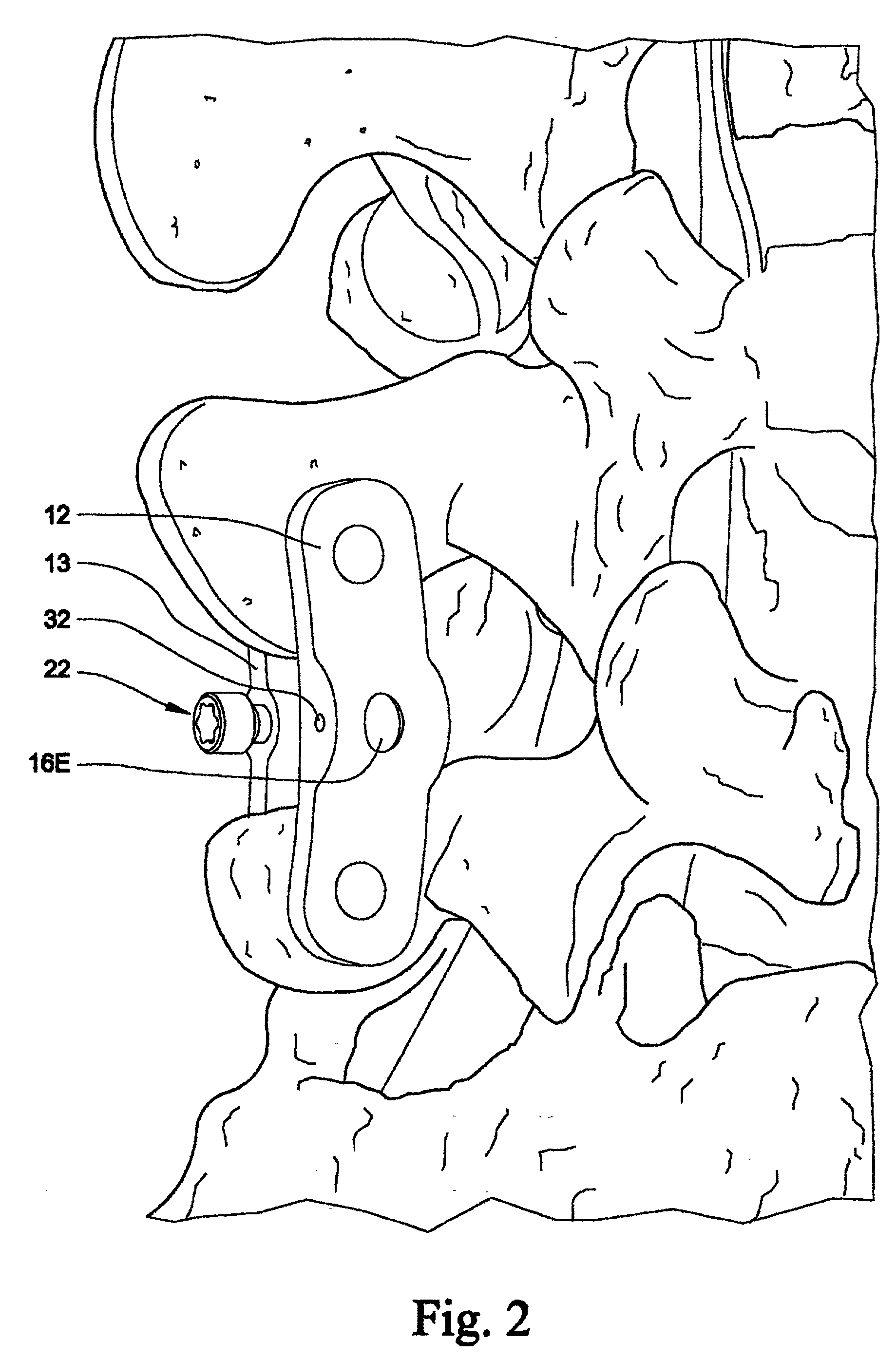
[0020]Referring now to the drawings in detail, particularly FIGS. 3 and 9, the device 11 according to the illustrated embodiment of the present invention, is clamped to the spinal processes of the L4 and L5 vertebrae. The device comprises a head plate 12, a locking plate 13, and a cross-post 14 having a head 16 received in a socket 17 in the head plate, and a distal end 18 received through an aperture 19 in the ...


PUM


Abstract

A fixation device for use in association with ALIF procedures includes a couple of spaced plates having integral spikes on facing surfaces thereof for pressing into spinal processes of adjacent vertebrae. One of the plates has a spherical socket which captures a spherical head end of a post whose other end is received through an aperture in the other plate. The socket mounting is arranged to enable the post to pivot therein for at least two degrees of freedom to a limited extent, enabling angulation between the two plates so as to accommodate the different thicknesses and orientations of the spinal processes on adjacent vertebrae. The reception of the post in the second plate enables adjustment of spacing between the plates to accommodate effective installation of the assembly on the spinal processes by a compression instrument, and permanent reliable maintenance of that spacing following removal of the compression instrument. The cross-sectional configuration of the post and a receiver aperture in the plate inhibits rotation of the plate relative to the post about the post axis, and a set screw in the apertured plate engages a flat on the post fixing the inter-plate space as adjusted.

Description

BACKGROUND OF THE INVENTION[0001]1. Field of the Invention[0002]This invention relates generally to spinal surgery, and more particularly to devices for stabilization of the spine in association with placement of an inter-body construct for interbody fusion or the like.[0003]2. Description of the Prior Art[0004]Varieties of inter-body fusion devices are widely used following partial or total discectomies, for stabilization of the spine at the site. Some stabilization devices are anchored to the pedicles. With several systems, the use of the pedicles requires screws or other anchorage devices that occupy significant space and involve muscle dissection and associated work time for implantation. We believe that such elaborate apparatus and procedures are unnecessary in many instances.[0005]Breard et al. U.S. Pat. No. 5,011,484 issued Apr. 30, 1991 discloses an artificial ligament used with an elongate insert. A couple of types of systems, one including rods and another including inexte...

Claims


Application Information

Patent Timeline
Patent Type & Authority Patents(United States)
IPC IPC(8): A61B17/70A61B17/58
CPCA61B17/7068A61B17/70
Inventor ROBINSON, JAMES C.WISNEWSKI, PAULBLACKWELL, JONATHANNULL, W. BARRY
Owner WARSAW ORTHOPEDIC INC
Why Eureka
Try Eureka