
Dual layer shingle

a technology of asphalt-based roofing and shingles, which is applied in the direction of record information storage, transportation and packaging, instruments, etc., can solve the problems of limited strength and life of shingles, extremely expensive as compared with ordinary oxidized asphalt, and relatively limited use of modified asphalt in roofing shingles, so as to achieve less costly and easy to apply

Active Publication Date: 2006-05-23
IKO INDS
View PDF23 Cites 55 Cited by
  • Summary
  • Abstract
  • Description
  • Claims
  • Application Information

AI Technical Summary

Benefits of technology

"The invention provides shingles that use a blend of modified and oxidized asphalt, which makes them less expensive and stiffer than shingles that use only modified asphalt. The stiffer shingles are easier to apply. The method involves coating a base sheet with asphalt layers, one of which contains an elastomeric polymer blend, and the other containing oxidized asphalt. The layers contact each other. The technical effect is a more durable and effective shingle that is easier to install."

Problems solved by technology

Since conventional oxidized asphalt which is normally used for roofing shingles has limited strength and life, and can be brittle, it has become common to use a form of asphalt which is referred to as “modified asphalt” for roofing shingles.
However, a disadvantage of modified asphalt is that it is extremely expensive as compared with ordinary oxidized asphalt.
Therefore, for economic reasons the use of modified asphalt in roofing shingles has been relatively limited.
In addition, roofing shingles which use modified asphalt may often be too flexible and can therefore be difficult to apply to a roof.
Further, because of their lack of stiffness they may tend to bend upwardly in a strong wind, increasing the likelihood (despite their greater strength) that they may eventually break.

Method used


Image

  • Dual layer shingle
  • Dual layer shingle
  • Dual layer shingle

Examples


Embodiment Construction

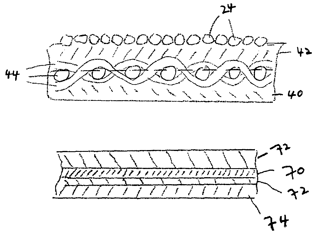
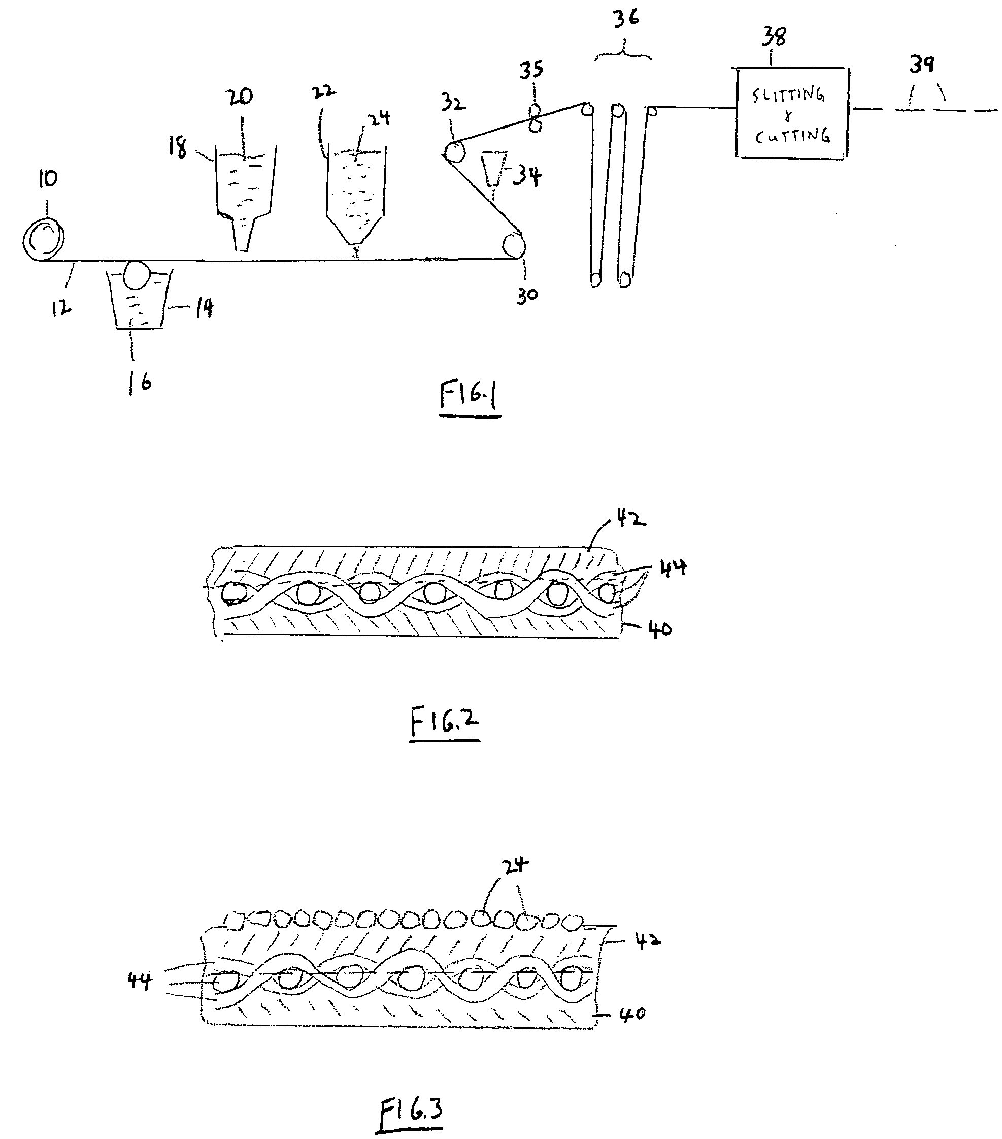
[0016]Reference is first made to FIG. 1, which shows a production line for shingles. The production line shown in FIG. 1 is conventional and therefore is described only briefly.

[0017]As shown, the production line includes a roll 10 of fiberglass mat or organic felt (normally the roll 10 will be fiberglass mat). A sheet 12 is unrolled from the roll 10 and passed over a conventional coater 14 containing conventional oxidized asphalt 16. The coater 14 coats the bottom of the sheet 12 with the oxidized asphalt 16.

[0018]The sheet 12 then passes beneath a top coater 18, which coats the top of the sheet 12 with modified asphalt 20. The differences between the modified asphalt 20 and the conventional asphalt 16 will be described below.

[0019]The sheet 12, now coated on both sides, next passes beneath a granule applicator indicated at 22, where granules 24 are applied to the top surface of the sheet 12. The sheet 12 then passes through rollers 30, 32 allowing the bottom surface of the sheet t...


PUM

PropertyMeasurementUnit
softening pointaaaaaaaaaa

Abstract

A shingle formed from a base sheet, with a layer of polymer modified asphalt coating the top of the base sheet, and a layer of conventional oxidized asphalt, free from polymer additives, coating the bottom of the base sheet. Both layers preferably directly contact the strands of the base sheet for good adhesion. This improves the strength, flexibility and ultraviolet resistance of the shingle, while reducing the cost as compared with a shingle which utilized only polymer modified asphalt, and in addition it increases the stiffness of the shingle as compared with one using only polymer modified asphalt.

Description

FIELD OF THE INVENTION[0001]This invention relates to asphalt-based roofing shingles for use on the roofs of buildings.BACKGROUND OF THE INVENTION[0002]Asphalt-based roofing shingles are commonly made by taking a continuous base sheet which may be of organic felt, or fiberglass mat, covering both sides of the base sheet with a coating asphalt, and then embedding granules on the top side of the coated sheet. The granules protect the asphalt from breaking down through oxidation caused by ultraviolet rays. The finished sheet is cut into lanes and then into desired lengths for shingles.[0003]Since conventional oxidized asphalt which is normally used for roofing shingles has limited strength and life, and can be brittle, it has become common to use a form of asphalt which is referred to as “modified asphalt” for roofing shingles. Modified asphalt has an elastomeric polymer blended with ordinary asphalt. The elastomeric polymer imparts elasticity and greater strength to the asphalt and al...

Claims


Application Information

Patent Timeline
Patent Type & Authority Patents(United States)
IPC IPC(8): E04D1/22B32B11/00E04D5/10B05D7/00B32B11/02B32B37/24C09D153/02C09D195/00D06N5/00E04B2/00E04D1/26E04D1/28
CPCB32B37/24E04D1/26D06N5/00B32B2315/085B32B2395/00Y10T428/2438E04D2001/005Y10T428/24355
Inventor KOSCHITZKY, HENRY
Owner IKO INDS
Learn More