Manipulation of live cells and inorganic objects with optical micro beam arrays

a micro-beam array and live cell technology, applied in the field of optical micro-beam array manipulation of live cells and inorganic objects, can solve the problems of limited number of trapping beams, limited methods, and inability to produce simple interference fringe patterns,

Inactive Publication Date: 2006-05-23
RGT UNIV OF CALIFORNIA
View PDF172 Cites 18 Cited by
  • Summary
  • Abstract
  • Description
  • Claims
  • Application Information

AI Technical Summary

Benefits of technology

[0022]The present invention contemplates the use of a vertical cavity surface emitting laser (VCSEL), or an array of VCSELs for the trapping of one or more microparticles. By the use of VCSELs bulky regular lasers are avoided. The multiple m

Problems solved by technology

First, a single beam can be split with a beamsplitter and recombined with refractive optics. See K. Sasaki et al., Optical Letters 16, 1463, 1991. This technique is limited by the number of trapping beams.
This method, producing simple interference fringe patterns, is limited.
Moreover, optical waveforms generated by holograms are

Method used


Image

  • Manipulation of live cells and inorganic objects with optical micro beam arrays
  • Manipulation of live cells and inorganic objects with optical micro beam arrays
  • Manipulation of live cells and inorganic objects with optical micro beam arrays

Examples


Embodiment Construction

[0069]The following description is of the best mode presently contemplated for the carrying out of the invention. This description is made for the purpose of illustrating the general principles of the invention, and is not to be taken in a limiting sense. The scope of the invention is best determined by reference to the appended claims.

[0070]Although specific embodiments of the invention will now be described with reference to the drawings, it should be understood that such embodiments are by way of example only and are merely illustrative of but a small number of the many possible specific embodiments to which the principles of the invention may be applied. Various changes and modifications obvious to one skilled in the art to which the invention pertains are deemed to be within the spirit, scope and contemplation of the invention as further defined in the appended claims.

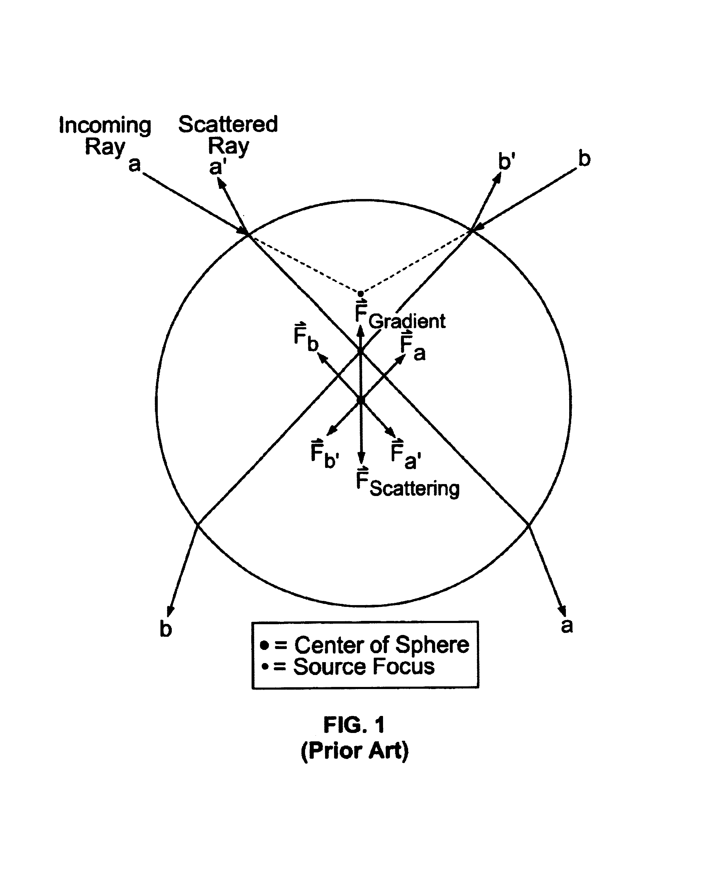
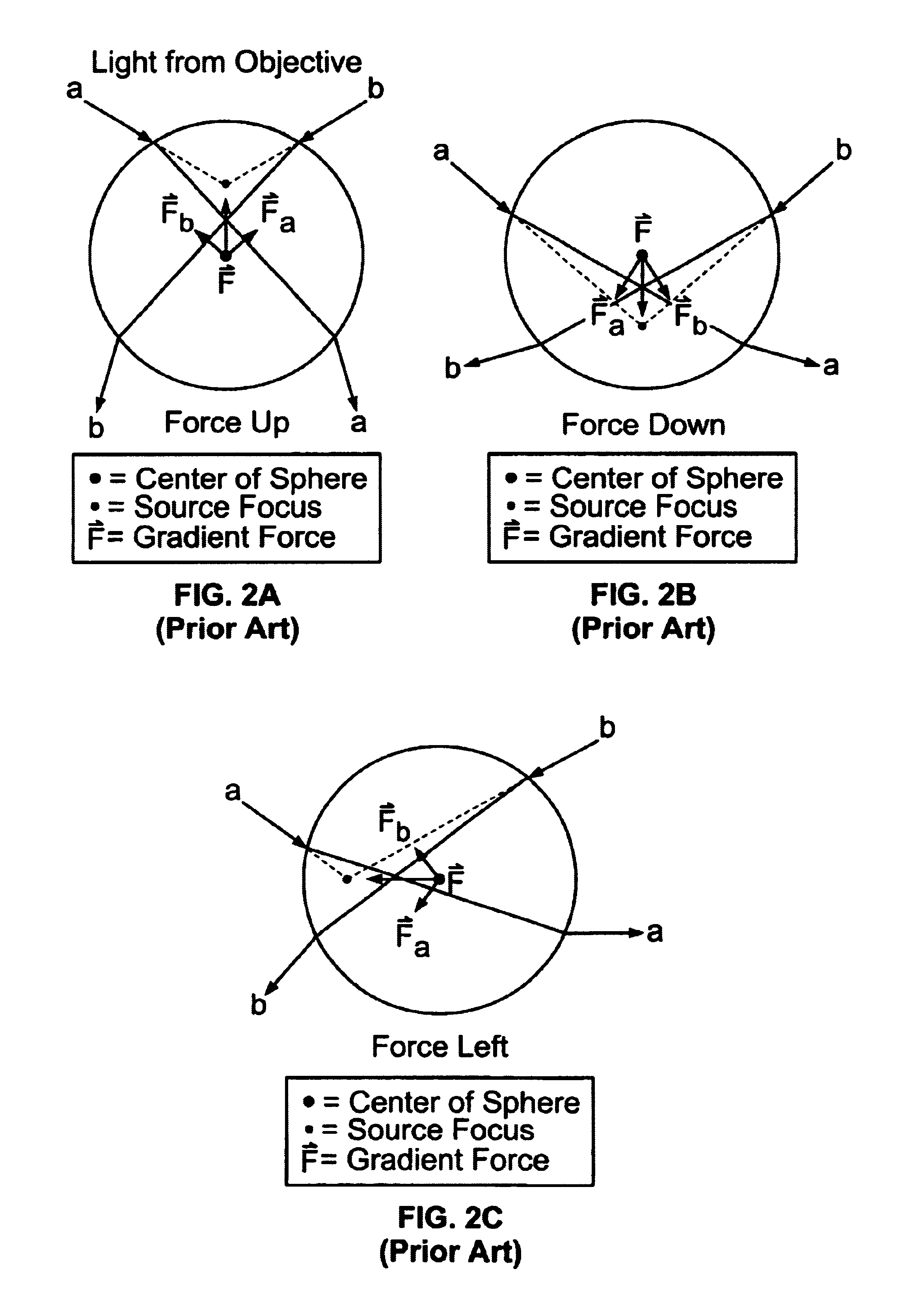
1. Principles of Optical Trapping / Tweezing, and Previous Trapping / Tweezing Apparatus

[0071]The gradient, and sca...


PUM


Abstract

One or more microbeams derived from a corresponding number of Vertical Cavity Surface Emitting Lasers (VCSELs) are used to manipulate and to transport inorganic and organic objects. The optical tweezing apparatus and method is compact size, and suitable to manipulate multiple objects in an array concurrently, and in parallel.

Description

RELATION TO A PROVISIONAL PATENT APPLICATION[0001]The present patent application is descended from, and claims benefit of priority of, U.S. provisional patent application Ser. No. 60 / 222,463 filed on Jul. 26, 2000 for VCSEL, and VCSEL Arrays, for Optical Tweezing of Organic and Inorganic Objects to the selfsame inventors as the present utility patent application.[0002]This invention was made by support of the U.S. Government under Grant No. MDA 972-98-1-001 to the Heterogeneous Optoelectronic Technology Center acting through the United States Defense Advanced Research Projects Agency (DARPA). The U.S. Government has certain rights in this invention.BACKGROUND OF THE INVENTION[0003]1. Field of the Invention[0004]The present invention generally concerns optical traps and tweezers for, and optical trapping and tweezing of, small and microscopic objects.[0005]The present invention particularly concerns (i) a laser and laser arrays for optical traps and tweezers, (ii) the structure and o...

Claims


Application Information

Patent Timeline
IPC IPC(8): H01S3/081G21K1/00H05H3/04
CPCH05H3/04G02B21/32
Inventor OZKAN, MIHRIMAHESENER, SADIKWANG, MARK
Owner RGT UNIV OF CALIFORNIA
Why Eureka
Try Eureka