Incandescent bulb and incandescent bulb filament

a technology of incandescent bulbs and filaments, which is applied in the direction of discharge tubes/lamp details, discharge tubes/lamp details, incadescent body mounting/support, etc., can solve the problems of low lamp efficiency of only about 13 im/w, lower lamp efficiency, and element b>50/b>′ which does not allow the surface temperature to be maintained constant, etc., to achieve high lamp efficiency

Active Publication Date: 2006-05-23
PANASONIC CORP
View PDF9 Cites 41 Cited by
  • Summary
  • Abstract
  • Description
  • Claims
  • Application Information

AI Technical Summary

Benefits of technology

[0011]The present invention has been conceived in view of the above problems, and it is an object of the present invention to provide an incandescent bulb of a simple structure which has high lamp efficiency and has surface light-emitting capability, and a filament for use with the incandescent bulb.
[0016]It becomes possible, using these microcavities, to select arbitrary wavelengths for suppressing the radiation and thus to use the suppressed energy for visible light. Therefore, a filament of high lamp efficiency is provided.
[0018]By such an arrangement of spaced portions, it becomes possible to retain the generated heat around the filament, that is, to form a so-called sheath efficiently, and therefore to improve the lamp efficiency.

Problems solved by technology

However, a standard incandescent bulb radiates electromagnetic waves including about 90 percent of infrared radiation and only about 10 percent of visible light.
Such an incandescent bulb has low lamp efficiency of only about 13 Im / W, which poses a challenge to improvement in lamp efficiency.
However, even such a reflex lamp has far lower lamp efficiency than a fluorescent lamp, and therefore its lamp efficiency needs to be improved more.
In other words, a bulb including the light-emitting element 50′ which does not allow its surface temperature to be maintained constant has low lamp efficiency.

Method used


Image

  • Incandescent bulb and incandescent bulb filament
  • Incandescent bulb and incandescent bulb filament
  • Incandescent bulb and incandescent bulb filament

Examples


first embodiment

[0047]A description of the first embodiment is given below with reference to the diagrams.

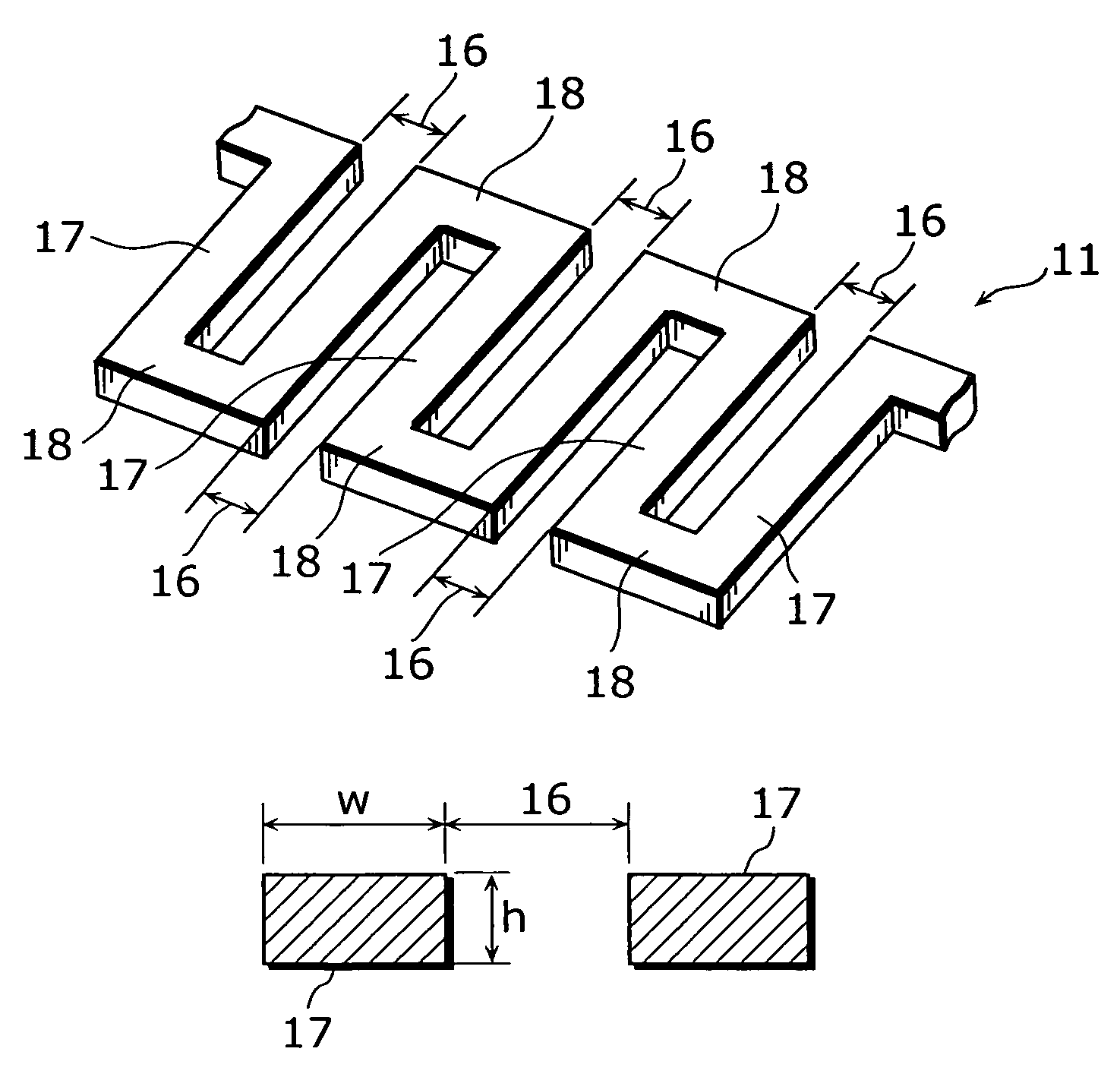
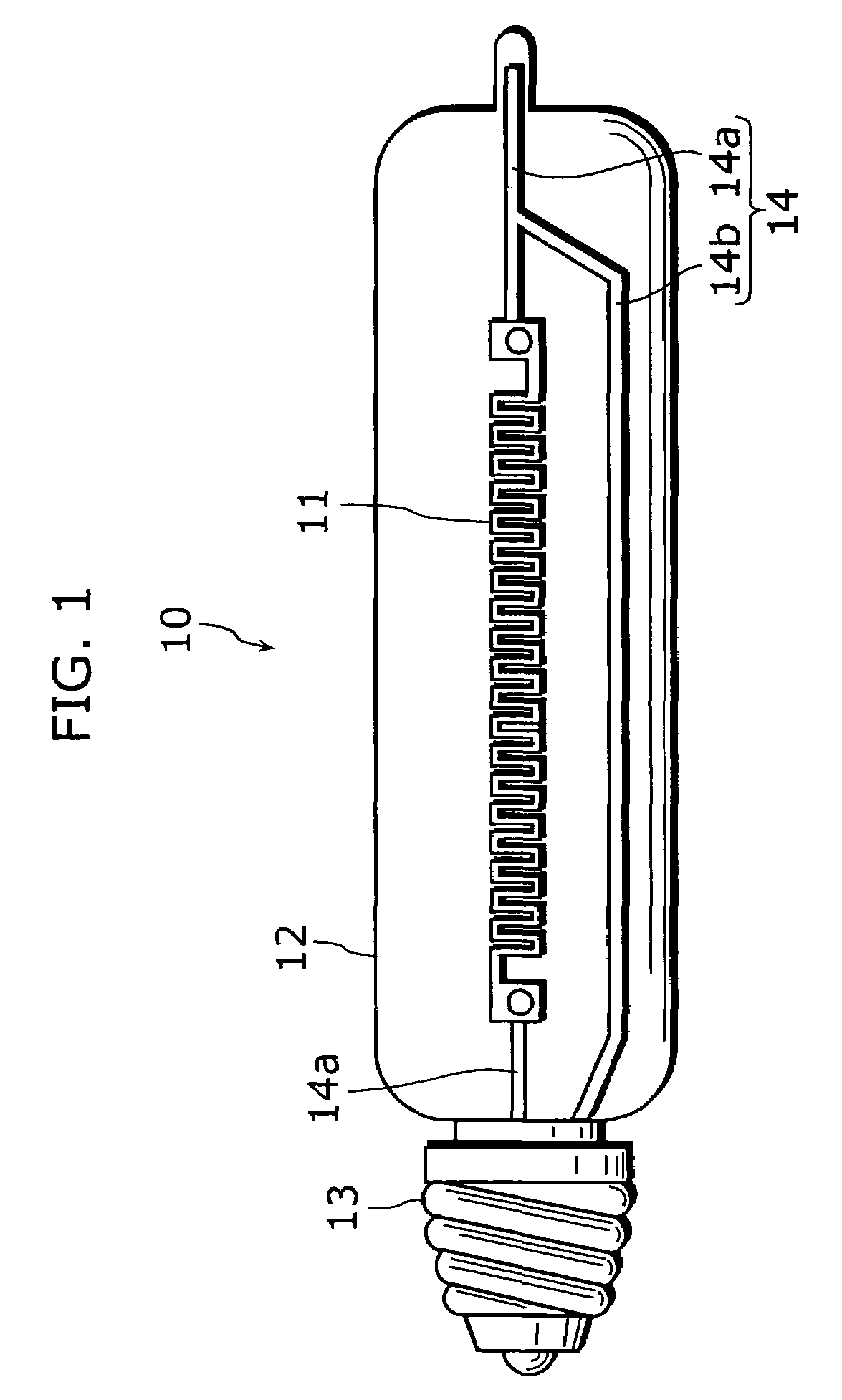
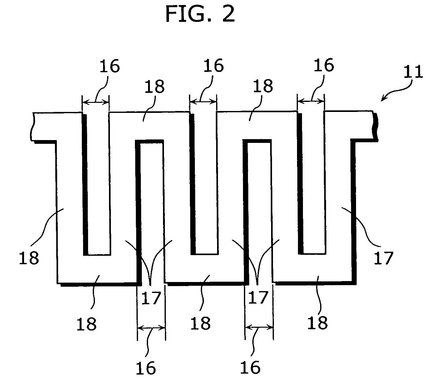
[0048]In the present embodiment, the structure of an incandescent bulb 10, each filament space 16, and relationship between each filament space 16 and a relative proportion of a gas filled into a bulb 12. FIG. 1 is a schematic diagram of an incandescent bulb 10 in the present embodiment and a perspective view of the bulb 12 made of glass. FIG. 2 is an enlarged view of a part of a filament 11 of the present embodiment. FIG. 3 is a perspective view showing the part of the filament 11.

[0049]First, the structure of the incandescent bulb 10 is described.

[0050]As shown in FIG. 1, the incandescent bulb 10 includes the filament 11 made of a thin film, the bulb 12 provided so as to envelop the filament 11, a noble gas (not shown in the diagram) filled in the bulb 12, a base 13 provided so as to close up the opening of the bulb 12, a lead-in wire 14 which is provided in parallel to the longitudinal direc...

second embodiment

[0086]A description of the second embodiment is given below with reference to the diagrams.

[0087]In the present embodiment, a description is focused on the structure of an incandescent bulb 20. FIG. 6 is a schematic diagram showing a perspective view of the incandescent bulb 20 in the present embodiment when viewed through the glass that forms a bulb 22. FIG. 7 is an enlarged view of a filament 21 in the present embodiment.

[0088]Differently from the incandescent bulb 10 in the first embodiment, the incandescent bulb 20 in the present embodiment includes the filament 21 having a round shape appearance, and therefore the shapes of the bulb 22 and the lead-in wire 24 are different from those of the first embodiment. Everything else is identical to the incandescent bulb 10 and the filament 11 in the first embodiment. Therefore, a detailed description of the overlap between these embodiments is not repeated here.

[0089]As shown in FIG. 6, the incandescent bulb 20 includes the filament 21 ...

third embodiment

[0098]The incandescent bulb in the present embodiment is an incandescent bulb including a filament having microcavities. Before describing the present embodiment, a description of a microcavity is given.

[0099]Patent Document 1 discloses a method for increasing selectivity of wavelengths of electromagnetic radiation from a filament, namely, for preventing infrared radiation, by forming microcavities, as a means for increasing the lamp efficiency of an incandescent bulb, on the surface of the filament that is the light-emitting surface and using a quantum effect of these microcavities. In this method, a microcavity is a square column in shape having a square bottom with a length of each side of about the wavelength of visible light and a depth longer than the wavelength of visible light (See Patent Document 1). Patent Document describes as follows. For example, if the surface of the filament has microcavities each having a square bottom with a side length of 350 nm and a depth around ...


PUM


Abstract

An incandescent bulb filament having a flat Light-emitting surface and high Lamp efficiency and an incandescent bulb using this filament are provided. This incandescent bulb filament is characterized in that it is a filament of ribbon shape placed on one plane, and it includes: spaced portions which are placed side by side with spaces; and connecting portions which connect the spaced portions electrically in series. Each spaced portion has a thickness that is one half the width of the spaced portion or more, and the space between at least one pair of adjacent spaced portions is less than five times the width of the spaced portion.

Description

CROSS REFERENCE TO RELATED APPLICATION[0001]This is a continuation of PCT application No. PCT / JP2004 / 019174 filed on Dec. 22, 2004.BACKGROUND OF THE INVENTION[0002](1) Field of the Invention[0003]The present invention relates to an incandescent bulb and an incandescent bulb filament, and particularly to an incandescent bulb filament of ribbon shape and an incandescent bulb using the filament.[0004](2) Description of the Related Art[0005]A standard incandescent bulb includes a filament made of a conductive material, a bulb which envelops the filament, and a noble gas which is filled in the bulb, and has a high color rendering property. This incandescent bulb is widely used because it can be lighted using simple fixtures without using a lighting circuit such as a ballast, differently from a discharge lamp, and because it has a long history of use. (See, for example, Japanese Laid-Open Patent Application No. 3-102701 (Patent Document 1) and Japanese Laid-Open Patent Application No. 6-3...

Claims


Application Information

Patent Timeline
Patent Type & Authority Patents(United States)
IPC IPC(8): H01K3/02H01K1/14
CPCH01K1/14
Inventor OHKUBO, KAZUAKIKIMOTO, MITSUHIKOKANEKO, YURIKOSAKAUE, MIKAHORIUCHI, MAKOTO
Owner PANASONIC CORP
Why Eureka
Try Eureka