Sizing of an electromagnetic transponder system for a dedicated distant coupling operation

a technology of electromagnetic transponder and distant coupling, applied in the direction of subscriber station connection selection arrangement, indirect connection of subscriber station, burglar alarm by hand-portable objects removal, etc., can solve the problems of inability to provide the desired security guarantees, inability to provide acceptable solutions, and inability to meet the requirements of remote coupling operation, etc., to achieve reliable in time and simple implementation

Inactive Publication Date: 2006-05-23
STMICROELECTRONICS SRL
View PDF123 Cites 27 Cited by
  • Summary
  • Abstract
  • Description
  • Claims
  • Application Information

AI Technical Summary

Benefits of technology

[0018]The present invention aims, in particular, at providing a solution that enables structurally dedicating a transponder and / or a terminal to an operation in a relatively distant range.
[0019]More generally, the present invention aims at providing a solution that enables structurally dedicating a transponder and / or a terminal to an operation in a relation where the antennas are at a distance greater than a predetermined value from each other.
[0020]The present invention also aims at providing a solution that is particularly simple to implement for the manufacturer and that is reliable in time.
[0021]To achieve these and other objects, the present invention provides an electromagnetic transponder of the type including a parallel oscillating circuit adapted to being excited by a series oscillating circuit of a read / write terminal when the transponder enters the field of the terminal, the components of the oscillating circuit of the transponder being sized so that the coupling coefficient between the respective oscillating circuits of the terminal and of the transponder rapidly decreases when the distance separating the transponder from the terminal becomes smaller than a predetermined value.

Problems solved by technology

In this case, conventional systems provide no acceptable solution.
Indeed, a transponder that would then be closer to the terminal could capture the information transmitted by the terminal to the distant transponder, which does not provide the desired guarantees in terms of security.
Further, a pirate terminal can then be interposed between the authorized terminal and the transponder and then intercept the transponder's information, which is not desirable either.
Another problem that is raised is that, in conventional systems, a transponder in a relatively distant coupling relation with a terminal will receive less power than a transponder placed closer to the terminal.
In such a case, the system operation risks suffering therefrom.

Method used


Image

  • Sizing of an electromagnetic transponder system for a dedicated distant coupling operation
  • Sizing of an electromagnetic transponder system for a dedicated distant coupling operation
  • Sizing of an electromagnetic transponder system for a dedicated distant coupling operation

Examples


Embodiment Construction

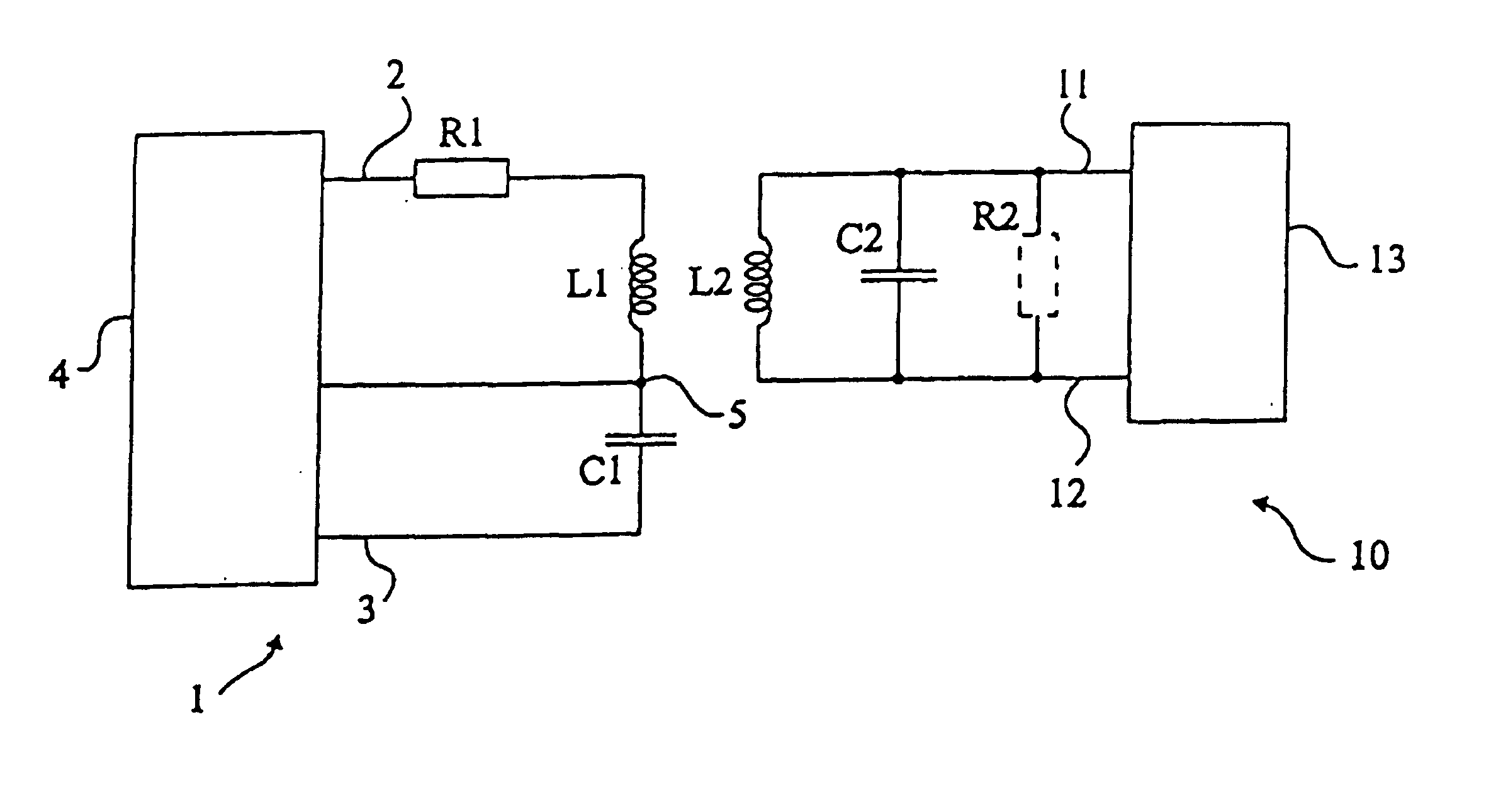
[0035]For clarity, only those elements necessary to the understanding of the present invention have been shown in the drawings and will be described hereafter. In particular, the circuits for controlling and exploiting the oscillating circuits of the transponder and of the terminal have not been detailed.

[0036]A feature of the present invention is to provide a specific sizing of the oscillating circuit of an electromagnetic transponder so that said transponder is structurally dedicated to an operation in a relatively distant range, that is, at more than 5 cm from a read / write terminal and, preferably, between 5 cm and the system range limit. This range depends on the transponder power consumption and is, for example, on the order of 20 to 30 cm for low-consumption transponders of tag type and on the order of 10 to 20 cm for transponders equipped with microcontrollers.

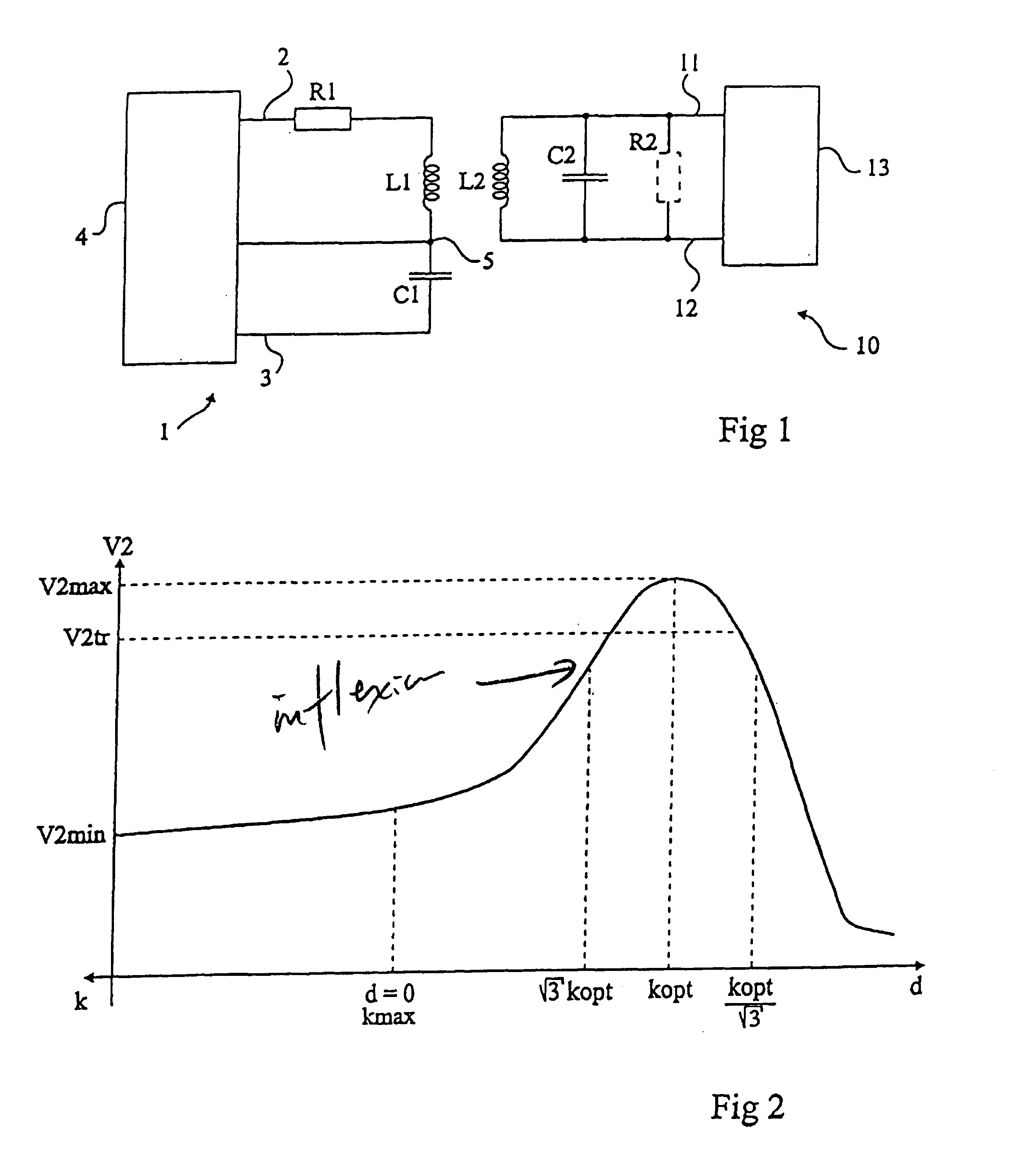
[0037]The notion of distance to which the present invention refers is the distance separating respective antennas L1,...


PUM


Abstract

A system of contactless electromagnetic transmission between a terminal including a series oscillating circuit for generating an electromagnetic field and a transponder including a parallel oscillating circuit, these oscillating circuits being sized so that the coupling coefficient between them rapidly decreases when the distance separating the transponder from the terminal becomes smaller than a predetermined value.

Description

BACKGROUND OF THE INVENTION[0001]1. Field of the Invention[0002]The present invention relates to systems using electromagnetic transponders, that is, transceivers (generally mobile) capable of being interrogated in a contactless and wireless manner by a unit (generally fixed), called a read and / or write terminal. The present invention more specifically relates to transponders having no independent power supply. Such transponders extract the power supply required by the electronic circuits included therein from the high frequency field radiated by an antenna of the read / write terminal. The present invention applies to such transponders, be they read only transponders, that is, adapted to operate with a terminal only reading the transponder data, or read / write transponders, which contain data that can be modified by the terminal.[0003]2. Discussion of the Related Art[0004]Systems using electromagnetic transponders are based on the use of oscillating circuits including a winding formin...

Claims


Application Information

Patent Timeline
Patent Type & Authority Patents(United States)
IPC IPC(8): H04Q5/22
CPCG06K19/0723
Inventor WUIDART, LUCENGUENT, JEAN-PIERRE
Owner STMICROELECTRONICS SRL
Why Eureka
Try Eureka