Compact fused disconnect switch

a fused disconnect switch, compact technology, applied in the field of disconnection switches, can solve the problems of disadvantaged fused disconnect switches of this type, limited field wiring options, and inability to meet the requirements of common line input bus use, etc., to achieve the effect of quick identification and replacemen

Inactive Publication Date: 2006-05-23
EATON INTELLIGENT POWER LIMITED
View PDF9 Cites 30 Cited by
  • Summary
  • Abstract
  • Description
  • Claims
  • Application Information

AI Technical Summary

Benefits of technology

[0009]A fused disconnect switch is therefore provided with a variety of wiring options including a common bus connection, without employing auxiliary components. Reliable local and remote fuse state indication is provided so that opened fuses may be quickly identified and replaced. A versatile, compact fused disconnect switch package is therefore provided that is better suited for applications wherein conventional fused disconnect switches have been found less than desirable, such as telecommunications applications.

Problems solved by technology

Known fused disconnect switches of this type, however, are disadvantaged in certain applications.
For instance, in telecommunications applications, increasing power demands of equipment loads have rendered many fused disconnect switches inadequate.
In addition, limited field wiring options can frustrate the use of a common line input bus and may require auxiliary components for connection to telecommunication distribution panels.
Conventional fuse state identification mechanisms are not as reliable as desired for telecommunications applications.
For at least the above reasons, use of fused disconnect switches have not completely met the needs of certain end applications, such as use in telecommunications systems.

Method used


Image

  • Compact fused disconnect switch
  • Compact fused disconnect switch
  • Compact fused disconnect switch

Examples


second embodiment

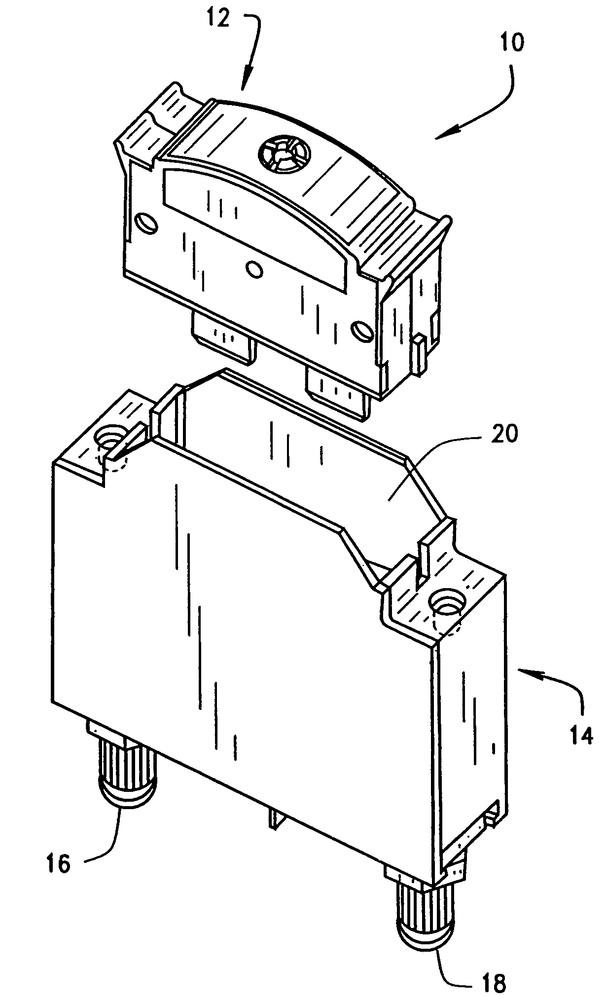
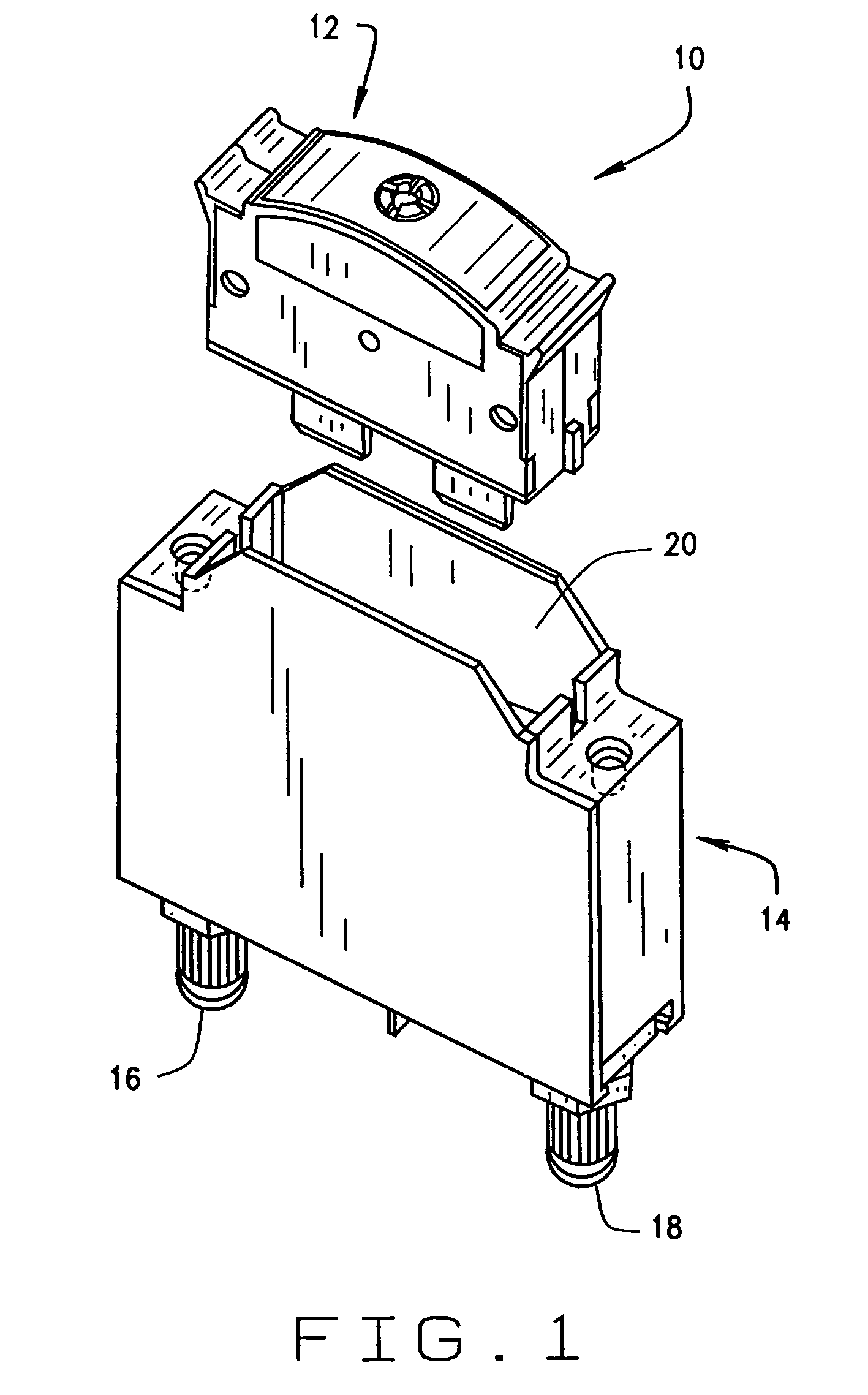
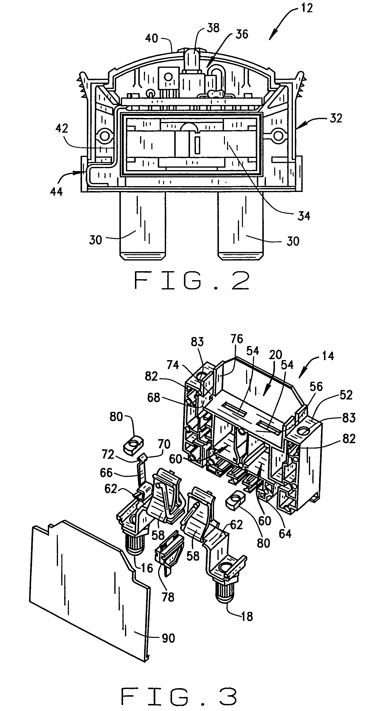
[0039]FIGS. 5 and 6 illustrate a switch housing assembly 100 for use with a fuse, such as fuse 12 (shown in FIG. 2) to form a fused disconnect switch assembly reminiscent of fused disconnect switch assembly 10 (shown in FIG. 1) but employing switch housing assembly 100 in lieu of switch housing assembly 14 (shown in FIG. 1).

[0040]Switch housing assembly 100 includes a housing 102 having fuse terminal openings 104 in a bottom 106 of fuse receptacle 108 for receiving fuse terminal blades 30 (shown in FIG. 2). An electrically conductive resilient clip 109 and associated reinforcing, pre-stressed wire spring element 111 is located below each fuse terminal opening 104 and located in a cavity 110 below fuse receptacle 108. A bridge portion 112 extends outwardly from each clip 109 and to a box style contact assembly 114 located in a wiring cavity 116 for connection to either a line input wire or bus (not shown) or a load wire (not shown). The stripped wires are inserted through wire input ...

third embodiment

[0046]FIGS. 7 and 8 illustrate a switch housing assembly 160 that combines the features of switch housing assemblies 14 and 100 (described above in relation to FIGS. 3 and 4 and FIGS. 5 and 6, respectively).

[0047]Switch housing assembly 160 may be employed with a fuse, such as fuse 12 (shown in FIG. 2) to form a fused disconnect switch assembly reminiscent of fused disconnect switch assembly 10 (shown in FIG. 1) but employing switch housing assembly 160 in lieu of switch housing assembly 14 (shown in FIGS. 1, 3 and 4).

[0048]Switch housing assembly 160 includes a housing 162 having fuse terminal openings 164 in a bottom 166 of fuse receptacle 168 for receiving fuse terminal blades 30 (shown in FIG. 2). An electrically conductive resilient clip 170, 171 and associated reinforcing, pre-stressed wire spring element 173 is located below each fuse terminal opening 164 and located in a cavity 172 below fuse receptacle 168. A bridge portion 174 extends downwardly from clip 170 and to an ele...

fourth embodiment

[0054]FIG. 9 is a perspective assembly view of a switch housing assembly 220 illustrating another field connection option as described below.

[0055]Switch housing assembly 220 may be employed with a fuse, such as fuse 12 (shown in FIG. 2) to form a fused disconnect switch assembly reminiscent of fused disconnect switch assembly 10 (shown in FIG. 1) but employing switch housing assembly 220 in lieu of switch housing assembly 14 (shown in FIGS. 1, 3 and 4).

[0056]Switch housing assembly 220 includes a housing 222 having fuse terminal openings 224 in a bottom 226 of fuse receptacle 228 for receiving fuse terminal blades 30 (shown in FIG. 2). An electrically conductive resilient clip 230, 232 is located below each fuse terminal opening 224 and located in a cavity 234 below fuse receptacle 228. A bridge portion 236 extends downwardly from clip 230 and to an electrically conductive bullet contact assembly 238 for connection to either a line input bus (not shown) or a load bus (not shown). A...


PUM


Abstract

A fused disconnect switch assembly includes a pull out fuse assembly and a switch housing assembly. The fuse assembly includes a line side conducting portion, a load side conducting portion, and a fuse element therebetween. The switch housing assembly includes a fuse receptacle for receiving the fuse, a first contact assembly coupled to the line side conducting portion of the fuse and a second contact assembly coupled to the load side conducting portion of the fuse when the fuse is inserted into the receptacle. An open fuse indication device is in communication with conducting portions of the fuse, and an alarm terminal output extends from the switch assembly housing and is in communication with the open fuse indication device. The open fuse indication device provides local fuse state indication and the alarm terminal output facilitates remote fuse state indication when coupled to external circuitry.

Description

CROSS REFERENCE TO RELATED APPLICATIONS[0001]This application is a continuation application of U.S. Application Ser. No. 09 / 892,007 filed Jun. 26, 2001, now issued U.S. Pat. No. 6,696,969, which claims the benefit of U.S. Provisional Application No. 60 / 215,441 filed Jun. 30, 2000.BACKGROUND OF THE INVENTION[0002]This invention relates generally to disconnect switches, and, more particularly, to fused disconnect switches.[0003]Fuses are widely used as overcurrent protection devices to prevent costly damage to electrical circuits. Fuse terminals typically form an electrical connection between an electrical power source and an electrical component or a combination of components arranged in an electrical circuit. One or more fusible links or elements, or a fuse element assembly, is connected between the fuse terminals, so that when electrical current through the fuse exceeds a predetermined limit, the fusible elements melt and opens one or more circuits through the fuse to prevent elect...

Claims


Application Information

Patent Timeline
Patent Type & Authority Patents(United States)
IPC IPC(8): G08B21/00H01H85/12H01H85/30H01H85/32H01H85/54H01H85/56H02H3/04
CPCH01H85/306H01H85/547H01H85/32H01H85/12H02H3/046H01H85/56
Inventor TORREZ, JAIME ALBERTOMOLLET, RONALD E.SCOGGIN, B. HEATH
Owner EATON INTELLIGENT POWER LIMITED
Why Eureka
Try Eureka