Integrated radar, optical surveillance, and sighting system

a radar and optical surveillance technology, applied in the direction of offensive equipment, using reradiation, instruments, etc., can solve the problems of human-based failure of the protection system, the response time required for a successful engagement of a potential threat may be lost, and the method of shipboard protection, etc., to achieve high durability and reliability, simple use, and easy installation

Active Publication Date: 2006-05-23
NAVY US GOVT AS REPRESENTED BY THE DEPT OF THE
View PDF7 Cites 42 Cited by
  • Summary
  • Abstract
  • Description
  • Claims
  • Application Information

AI Technical Summary

Benefits of technology

[0011]More specifically, the present invention is an integrated radar and optical (and, possibly, other component and / or) sensor, surveillance and sighting system (“IROS3”) that is capable of providing a “protective umbrella” around a military platform (or other entity of interest). (The terms “platform” and “entity of interest” (in any form) may be considered synonymous, and will be referred to hereinafter as “Platform”). In other words, the IROS3 integrates sensor information, communication data, and / or lethal and / or less-than-lethal / non-lethal engagement resources in order to provide an improved protection capability. Generally, the IROS3 is a potentially autonomous system that may be comprised of well-known, commonly used devices, components, and / or one or more of the Platform's other systems or subsystems.
[0019]Another feature of the present invention is that it could be effectively used in a variety of environments including, but not limited to, those constrained by personnel considerations, and / or those subject to vibrations due to the nature of the Platform in which the present invention is being used, e.g., on ships and / or vehicles.

Problems solved by technology

Moreover, it is often required that a ship's major combat systems (e.g., radar and / or sonar) must be secured (i.e., generally unavailable for use) due to a host nation's rules or regulations, or due to restrictions required by environmental rules and regulations.
There are disadvantages with the current methods of shipboard protection.
For example, the ability to successfully engage a potential threat is constrained by the timeliness of the detection and warning, by the number of personnel available for sentry duties, by the equipment currently used, and by other human perception and skill limitations (including a reduced probability of hit when compared to an automated system).
Clearly, these workplace conditions do not enhance the quality of life and may lead to human-based failures of the protection system.
Furthermore, if the sentry personnel do not identify a threat in a timely manner, the response time required for a successful engagement of a potential threat may be lost.
This may be exacerbated by requiring the sentry to relay the threat information to a remotely located supervisor prior to receiving authorization to engage the threat, which can cause further delays and, therefore, an increased likelihood of failure.
Lastly, with respect to the use of sentries, if the ship's personnel must engage a threat with a crew-manned weapon, those personnel are at risk of injury or death including the risks associated with return fire.
Other sources of failures may be attributable to the equipment being used, or to the combination of equipment and its user's human capabilities.
Some of the disadvantages of using binoculars are: limited range; limited field of view (especially when looking at one Contact while another Contact is approaching from another direction); a general dependency on fair weather; and the requirement to be hand-held, which can increase the time needed to man a weapon or which can impede the use of a hand-held radio.
Likewise, communications using hand-held radios may be limited by the capability of the sentry to describe the on-going events.
The sentry must paint a verbal picture of these events, which can lead to misinformation, incorrect information, or untimely information—all of which may lead to a tactical disadvantage.
Another potential disadvantage is attributable to a ship's RHIB.
This wastes fuel, time, and / or other resources, and generally increases the need for additional maintenance and / or other services—all of which increase costs.
Furthermore, engagement of a non-threat Contact may place the RHIB out of position to engage a real threat.

Method used


Image

  • Integrated radar, optical surveillance, and sighting system
  • Integrated radar, optical surveillance, and sighting system
  • Integrated radar, optical surveillance, and sighting system

Examples


Embodiment Construction

[0024]While the following discussion illustrates preferred embodiments of the present invention, it does not limit the present invention from being implemented (and / or configured) in a myriad of other manners within the spirit and scope of this Application. Moreover, while the devices, software, circuits, and / or other components used in the present invention preferably come from the group of devices, software, circuits, and / or other components that are well-known, and / or are commonly (or readily made) available, other means of implementing the present invention may also be used as well. Furthermore, while the name being used herein for the present invention is “Integrated Radar, Optical Surveillance, and Sighting System,” it should not be considered that the present invention is limited to using only the named systems, subsystems, and / or components (i.e., “Radar” and / or “Optical” related systems, subsystems, and / or components).

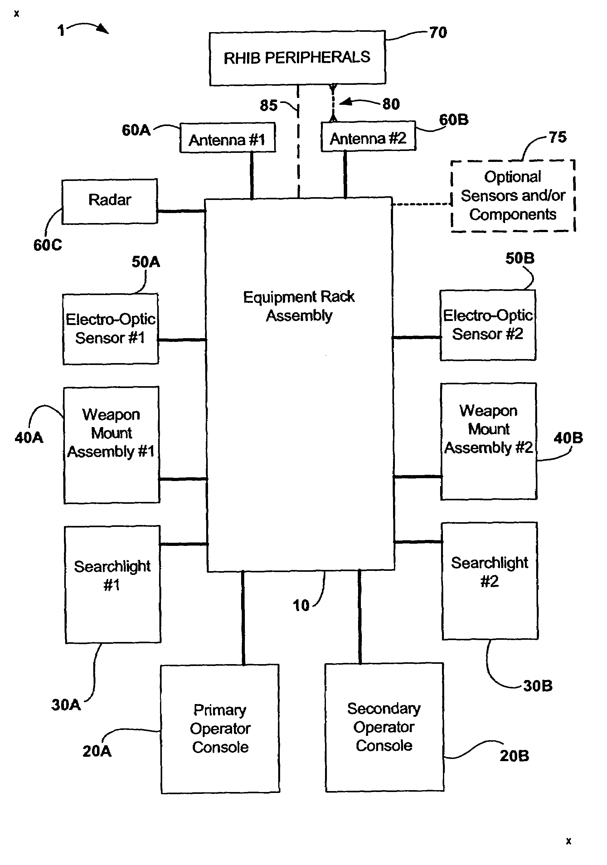
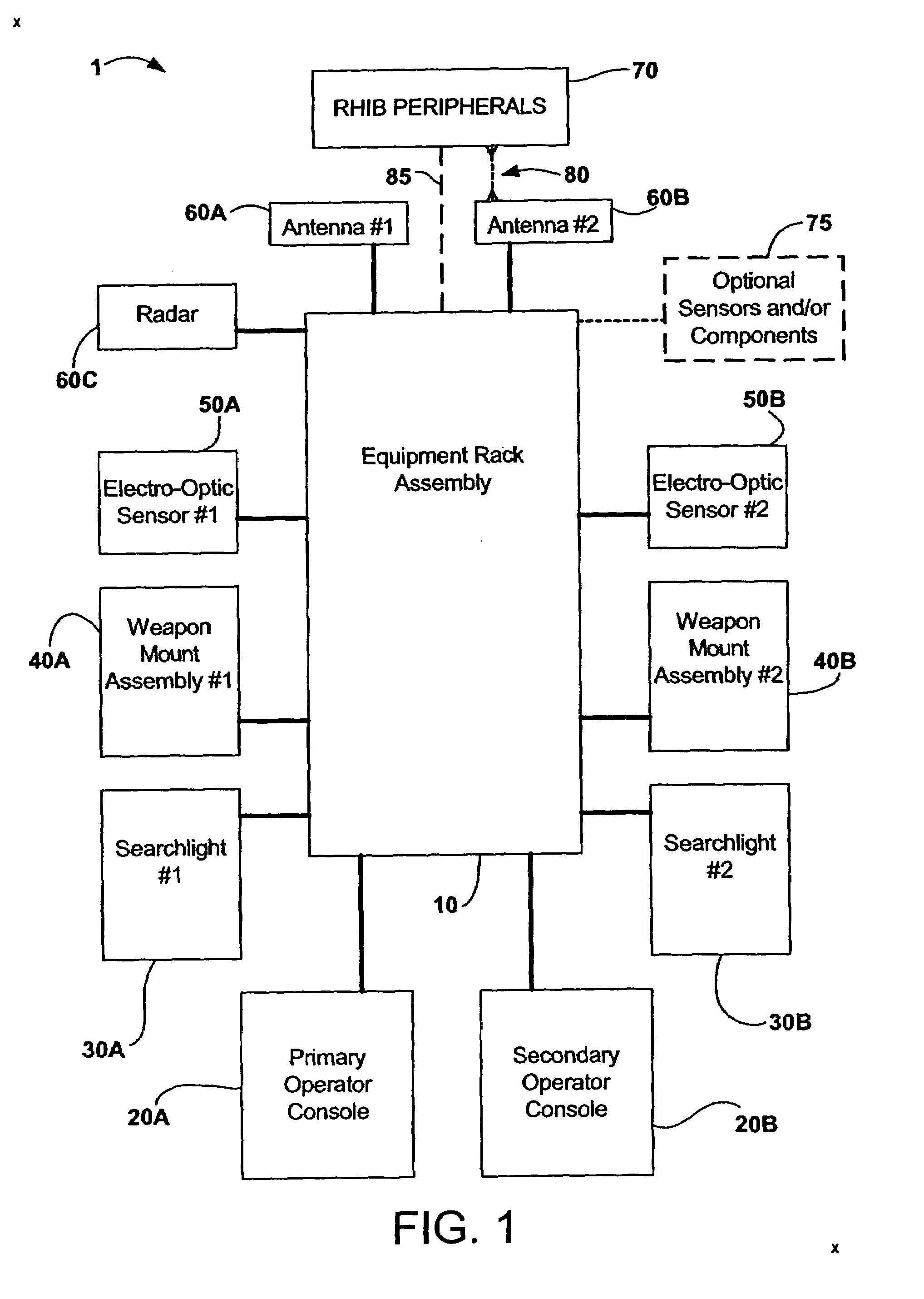
[0025]Referring now to FIG. 1, a block diagram illustrat...


PUM


Abstract

The present invention can be generally described as a protection system. This protection system is formed by the integration of commonly available subsystems, which may be controlled by non-proprietary, open architecture software, which, in turn, may accommodate the commonly known “plug and play” capability. This allows the present invention to easily incorporate a variety of lethal (or less-than-lethal) weapon payloads as well as a variety of sensors and detectors; thereby providing the user with the first real, integrated system (of systems) solution capable of providing an enhanced situational awareness capability.

Description

CROSS REFERENCE TO RELATED APPLICATIONS[0001]This application is a continuation, and claims the benefit, of U.S. Nonprovisional application Ser. No. 10 / 943,648, filed on Sep. 10, 2004, now U.S. Pat. No. 6,903,676, which is incorporated herein by reference. Applicant claims the priority date benefits of that application.STATEMENT REGARDING FEDERALLY SPONSORED RESEARCH OR DEVELOPMENT[0002]The invention described herein may be manufactured and used by or for the Government of the United States of America for governmental purposes without payment of any royalties thereon or therefor.REFERENCE TO A SEQUENCE LISTING, A TABLE, OR A COMPUTER PROGRAM LISTING COMPACT DISK APPENDIX[0003]Not Applicable.BACKGROUND OF THE INVENTION[0004]The present invention generally relates to a system capable of detecting, tracking, and, possibly, engaging one or more objects of potential concern, and more particularly, but without limitation, to a system of instruments (and / or components) capable of providing...

Claims


Application Information

Patent Timeline
Patent Type & Authority Patents(United States)
IPC IPC(8): G01S13/86F41H11/00G01S7/00G01S13/72
CPCF41H11/00G01S13/867G01S13/723G01S7/003B63G13/00
Inventor FRADY, TRENT J.WILSON, DUSTIN L.WERNER, KYLE R.MOODY, ERIC S.FLYNN, NANCY J.KONERMAN, MICHAEL P.SCHMIDT, PAUL L.MULLEN, ROBERT E.KOI, MARK R.WASIL, NIGEL G.DAUGHERTY, MICHAEL G.MEHRINGER, BRET R.
Owner NAVY US GOVT AS REPRESENTED BY THE DEPT OF THE
Why Eureka
Try Eureka