Supercharge Your Innovation With Domain-Expert AI Agents!

Multi-channel image encoding method and system

a multi-channel image and encoding technology, applied in the field of encoding systems, can solve the problems of increasing system cost, not effectively encoding a plurality of input signals in a multi-channel environment, and not effectively removing temporal redundancy, so as to achieve the effect of stabilizing frame ra

Inactive Publication Date: 2006-05-23
4NSYS
View PDF12 Cites 2 Cited by
  • Summary
  • Abstract
  • Description
  • Claims
  • Application Information

AI Technical Summary

Benefits of technology

[0013]Another object of the present invention is to supply multi-channel image encoding system that stabilize frame rate under the conditions that the multi-channel input video signals are sharing hardware resources.

Problems solved by technology

Since conventional MPEG encoders have been designed for encoding a single channel video signal, they can not effectively compress a plurality of signals in an multi-channel environments.
However, it can not effectively remove temporal redundancy because a large memory is needed in order to store previous frames (hereinafter, restoring frames) and current frames (hereinafter, input frames) for each of input channels.
And yet this scheme increases the system cost and results in an inefficient system.
However, designing an MPEG multi-channel encoder that uses common hardware such as memories has been found difficult because it experienced fluctuation in the frame rate during the course of MPEG encoding.
However, the periods of the synchronization signals are not identical.
For example, security cameras made by a same manufacture would not produce exactly the same synchronization signals.
These variations cause frame rate fluctuation.
Because the problem of frame rate fluctuation was not solved, a multi-channel MPEG encoding system has not been developed.

Method used


Image

  • Multi-channel image encoding method and system
  • Multi-channel image encoding method and system
  • Multi-channel image encoding method and system

Examples


Embodiment Construction

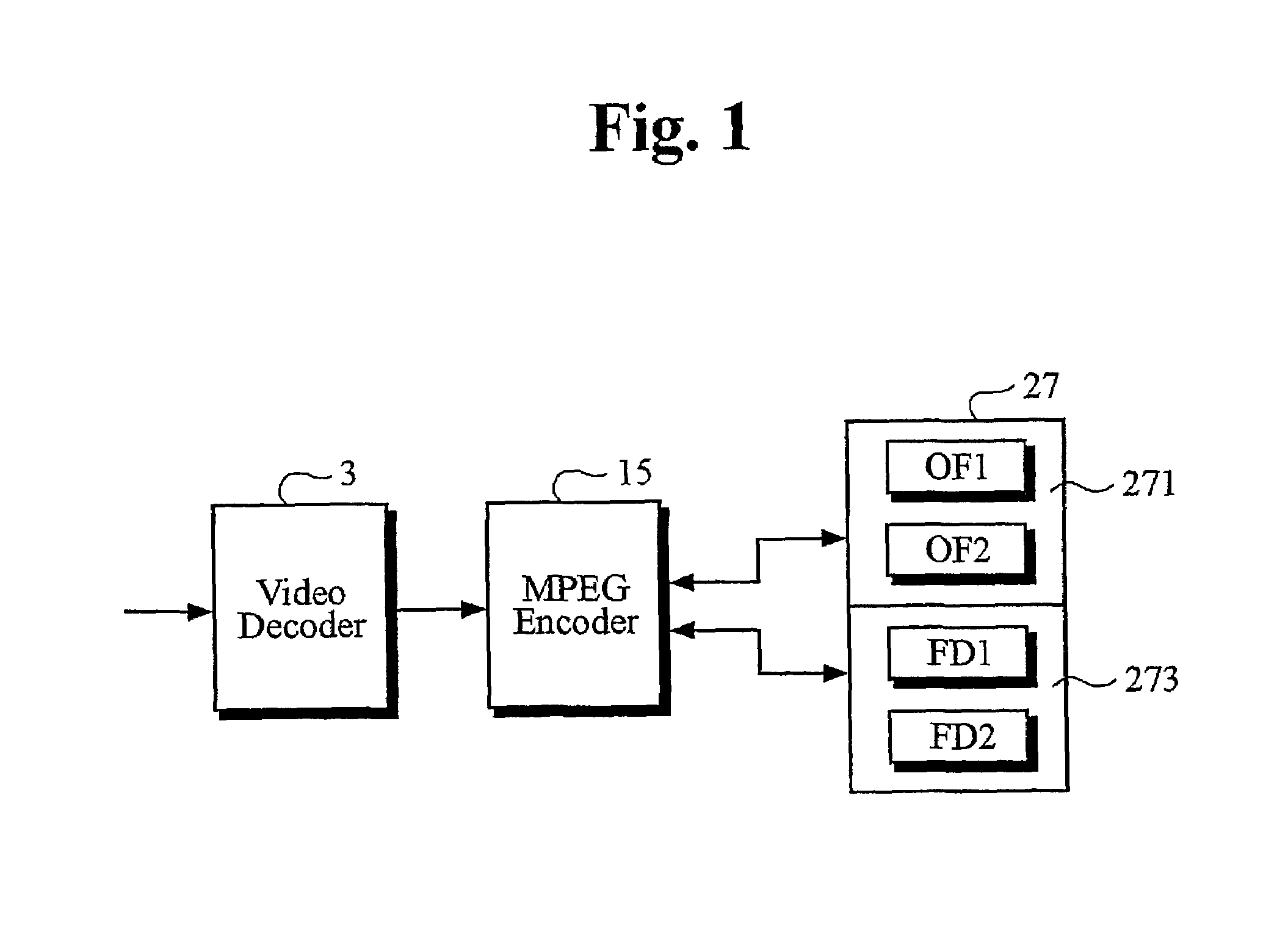
[0027]FIG. 1 shows a conventional single-channel MPEG encoding system. A video decoder 3 transforms analog or digital input video signals into digital signals in a format that an MPEG encoder 15 can interpret. The MPEG encoder encodes digital video signals into MPEG signals. During the MPEG encoding process, current and previous frames of digital video signals are stored in a memory 27 for the purpose of eliminating temporal redundancy. Here, a frame is defined as a video image that is normally displayed on the display device at one instant of time. Memory 27 actually is comprised of an input frame memory 271 for storing a current frame and a restoring frame memory 273 for storing the previous frame.

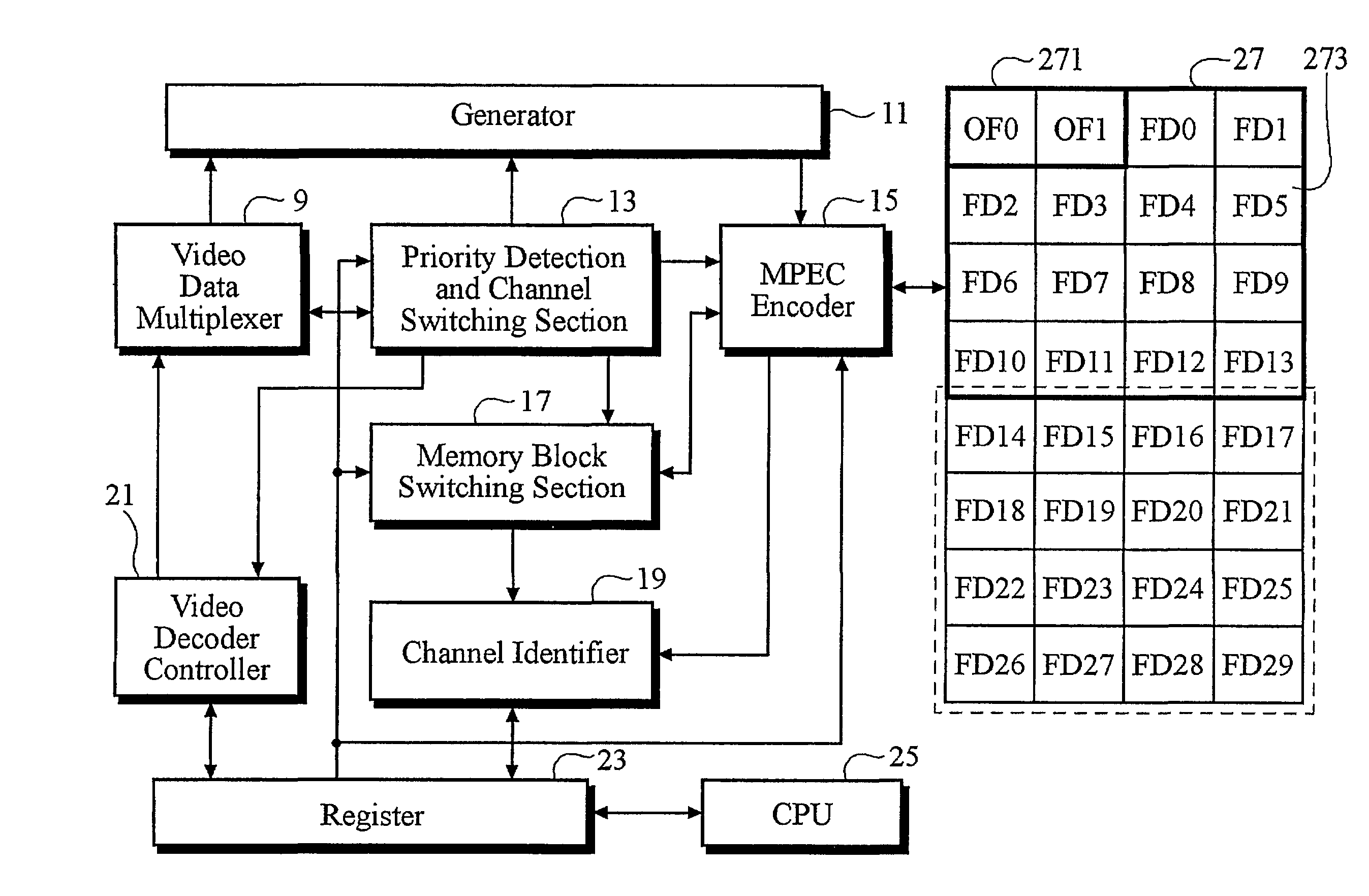
[0028]The input frame memory comprises at least two memory blocks while the number of memory blocks in the restoring frame memory is at least one more than the number of input channels. The memory capacity of each block should be large enough to store the data of one video frame because,...


PUM


Abstract

A method and apparatus for encoding multi-channel video signals is disclosed. In order for multiple of input channels to share hardware resources, one input channel is selected and multi-channel input video signals are stored through memory block switching. Multiplexer (1), video decoder (3), and digital video multiplexer (9) participate in selecting one input channel and memory block switching section (17) switches input and restoring frames to and / or from memory (27). For stabilizing frame rate under the conditions of multiple input channels, input channel sequence is determined by synchronization signal separator (7) and priority detection and channel switching section (13). In accordance with the present invention, multi-channel video signals are encoded into MPEG by using the conventional single channel MPEG encoder (15).

Description

TECHNICAL FIELD[0001]The present invention relates to encoding systems and, more particularly, to a method and apparatus for encoding a plurality of input signals with a minimal hardware requirements.BACKGROUND ART[0002]The basic principle of the MPEG coding, now widely used for compressing full-motion video data, is removing redundancies between signals. Examples of redundancies between signals are spectral redundancy, temporal redundancy, spatial redundancy and statistical redundancy. Spectral redundancy is found between spectral elements of RGB (Red, Green, Blue) image signals received from an input device such as cameras. Temporal redundancy means redundancy between images adjacent in time and can be removed by estimating and compensating any changes between two consecutive images. Spatial redundancy exists between adjacent pixels. Statistical redundancy is to be represented by statistical relation among coefficients generated during the MPEG encoding process. Statistical relati...

Claims


Application Information

Patent Timeline
IPC IPC(8): H04N7/12G06T9/00H04N7/26H04N7/50H04N21/2365H04N21/434
CPCH04N21/2365H04N19/42H04N19/61H04N21/4347
Inventor OH, TAEK MANHAHN, GHEE MAHN
Owner 4NSYS
Features
  • R&D
  • Intellectual Property
  • Life Sciences
  • Materials
  • Tech Scout
  • Unparalleled Data Quality
  • Higher Quality Content
  • 60% Fewer Hallucinations
Learn More