Identification of virtual raster pattern

a virtual and raster pattern technology, applied in the field of raster pattern identification, can solve the problems of poor position resolution, poor accuracy, and complicated processing of the detected position-coding pattern by the processor, and achieve the effect of high degree of accuracy

Inactive Publication Date: 2006-05-23
ANOTO AB
View PDF12 Cites 113 Cited by
  • Summary
  • Abstract
  • Description
  • Claims
  • Application Information

AI Technical Summary

Benefits of technology

[0014]A special object is to make possible the identification of a regular virtual raster pattern in an image that is recorded with an unknown rotation and / or an unknown perspective between the imaging sensor and the imaged surface.
[0035]The perspective compensation suitably comprises measuring an inclination variation for the raster pattern along each main vector in the rotation-corrected image, calculating a perspective transform that essentially eliminates the inclination variation on the basis of the measured inclination variation, and producing a perspective-corrected image by means of the perspective transform. This is an efficient way to calculate a perspective-corrected image with a high degree of accuracy.

Problems solved by technology

A problem with the position-coding pattern of U.S. Pat. No. 5,852,434 is that it is constructed of complex symbols and the smaller the symbols are made, the more difficult it becomes to produce the patterned writing surface and the greater the danger of incorrect position determinations, while the larger the symbols are made, the poorer the position resolution becomes.
A further problem is that the processing of the detected position-coding pattern by the processor becomes rather complicated, due to the fact that complex symbols are to be interpreted.
Yet another problem is that the sensor must be designed in such a way that it can record four symbols at the same time, so that it is certain to include at least one symbol in its entirety, which is necessary in order for the position determination to be carried out.

Method used


Image

  • Identification of virtual raster pattern
  • Identification of virtual raster pattern
  • Identification of virtual raster pattern

Examples


Embodiment Construction

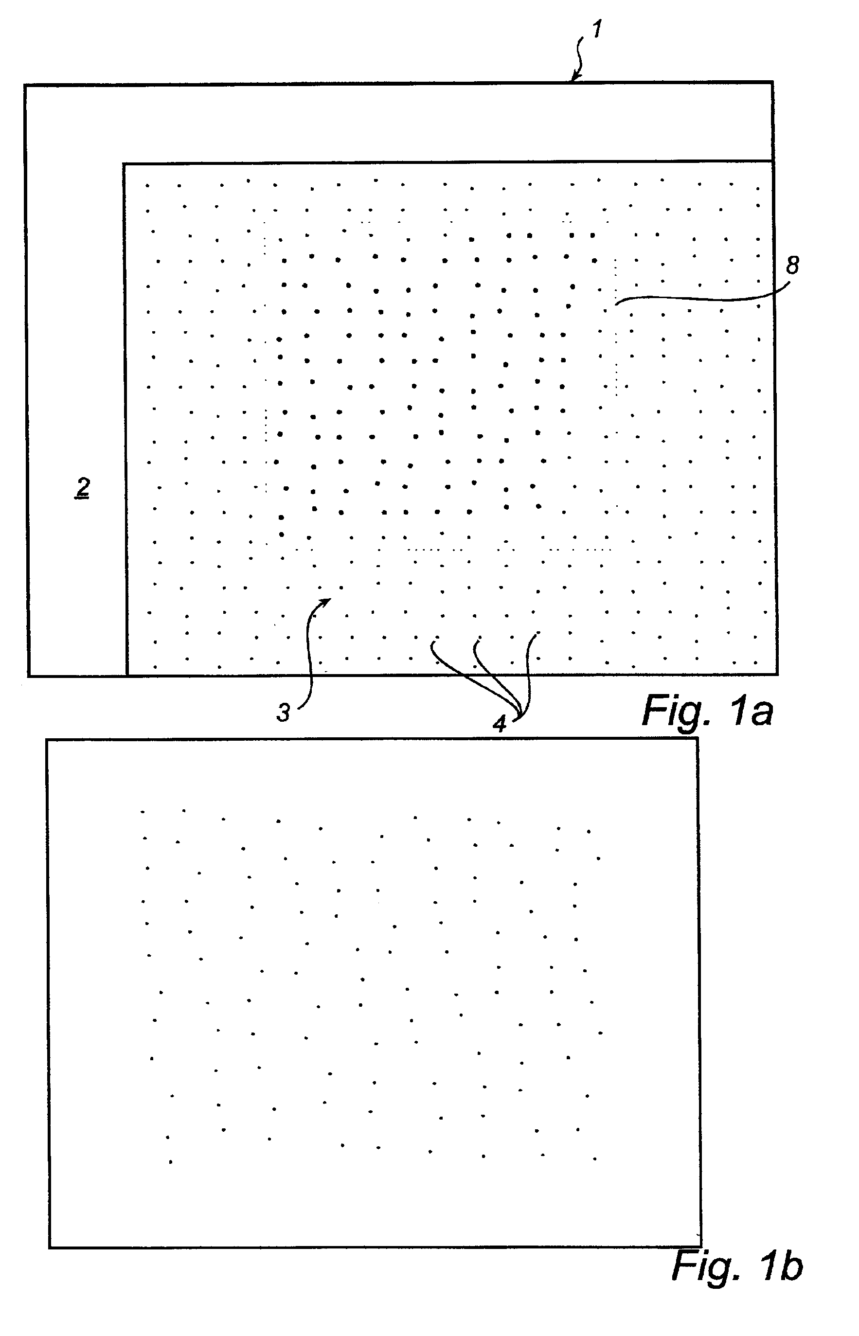
[0056]FIG. 1a shows a part of a product 1 which on at least part of its surface 2 is provided with an optically readable position-coding pattern 3 which makes possible position determination. The position-coding pattern 3 comprises marks 4 which are systematically arranged across the surface, so that this has a “patterned” appearance. The position determination can be carried out on the whole surface of the product. In other cases, the surface that permits position determination can constitute a smaller part of the product. The product can, for example, be used to produce an electronic representation of information that is written or drawn on the surface. The electronic representation can be produced by determining the position of a pen on the paper continually while writing on the surface with the pen, by reading off the position-coding pattern.

[0057]More particularly, the position-coding pattern comprises a virtual raster 5 (indicated by broken lines in FIG. 9), which is neither v...


PUM


Abstract

A method aims to identify a virtual raster pattern in an image of a surface that is provided with a plurality of position-coding marks. Each mark is associated with a respective intersection of raster lines belonging to the raster pattern. By means of the method, the virtual raster pattern is identified via Fourier analysis of the image. A computer program product and a device for position determination are also described.

Description

[0001]This application claims the benefit of provisional applications 60 / 210,647 and 60 / 261,123, filed Jun. 9, 2000 and Jan. 12, 2001 respectively.TECHNICAL FIELD[0002]The present invention relates in general to identification of raster patterns, in particular in connection with position coding on a surface that is provided with a plurality of position-coding marks. In particular, the invention relates to identification of a virtual raster pattern in an image of this surface, on which each mark is associated with a respective intersection of raster lines belonging to the virtual raster pattern.BACKGROUND ART[0003]In many connections it is desirable to be able to determine an absolute position on a surface. One example is the digitizing of drawings. Another example is the production of an electronic version of handwritten information.[0004]Examples of previously known devices for position determination are found in U.S. Pat. No. 5,852,434, where a device for determining an absolute p...

Claims


Application Information

Patent Timeline
Patent Type & Authority Patents(United States)
IPC IPC(8): G06K9/36G06F3/03G06F3/033G06K7/14G06K19/06
CPCG06F3/0317G06F3/03545G06K9/22G06K19/06037G06K7/14G06K2009/226G06F3/0321G06V10/17G06V10/19
Inventor EDSO, TOMASERICSON, PETTER
Owner ANOTO AB
Why Eureka
Try Eureka