Eureka AIR delivers breakthrough ideas for toughest innovation challenges, trusted by R&D personnel around the world.

Through-the-earth communication system

Inactive Publication Date: 2006-05-23
TRANSTEK
View PDF20 Cites 32 Cited by
  • Summary
  • Abstract
  • Description
  • Claims
  • Application Information

AI Technical Summary

Benefits of technology

[0013]At each location, the RF transceivers are connected to a control unit. A control unit, which may be designated as either a master or interface unit, provides power to the transceivers and allows for bi-directional communication of audio or voice, control and status information between the control unit and each transceiver. In this way, the control unit can force the RF transceiver to transmit an audio signal so that anyone within range of the transceiver hears the audio message on their portable hand-held radio. Similarly, when anyone within range of RF transceiver wishes to communicate with another individual, they are enabled to talk into their portable hand-held radio, while pushing the “talk” or “transmit” button, for example. The nearest RF transceiver receives the broadcast and informs the control unit to which the nearest RF transceiver is connected that the transceiver is receiving a valid RF broadcast. The RF transceiver also sends demodulated voice signal to the control unit. In cases where the transmission / reception ranges of the RF transceivers overlap, such that several control units may receive the same RF signal through their corresponding RF transceivers, the control units have the ability to determine the strength of the received signal at the RF transceiver. In this way, only the control unit that is receiving the strongest signal may send the received signal to all other control units in the network. The signal may be digitized.
[0020]The present invention also includes a novel method of connections between multiple power systems or phases. Traditional system of using a capacitor bridge only to connect multiple power systems does not work reliably when more than two power systems are being connected. Using more than one capacitor bridge in a system, for example, to connect more than two power systems to the same powerline communications network does not work with the traditional systems. To overcome the shortcomings of the traditional systems, the novel bridging method leaves two power systems or phases that are being bridged as independent and galvanically-isolated with only a galvanically-isolated RS-232 serial connection between the two power systems or phases. In this way, network data, e.g., digitized voice and digital process data, may be passed between two powerline communications modules, one on each power system or phase, thereby effectively bypassing the AC powerline medium and instead using a dedicated, galvanically-isolated high-speed serial connection so that the two power systems or phases are left isolated.

Problems solved by technology

In these environments, person-to-person wireless communications are not feasible using traditional communications devices.

Method used


Image

  • Through-the-earth communication system
  • Through-the-earth communication system
  • Through-the-earth communication system

Examples


Embodiment Construction

Facility-wide Communication System

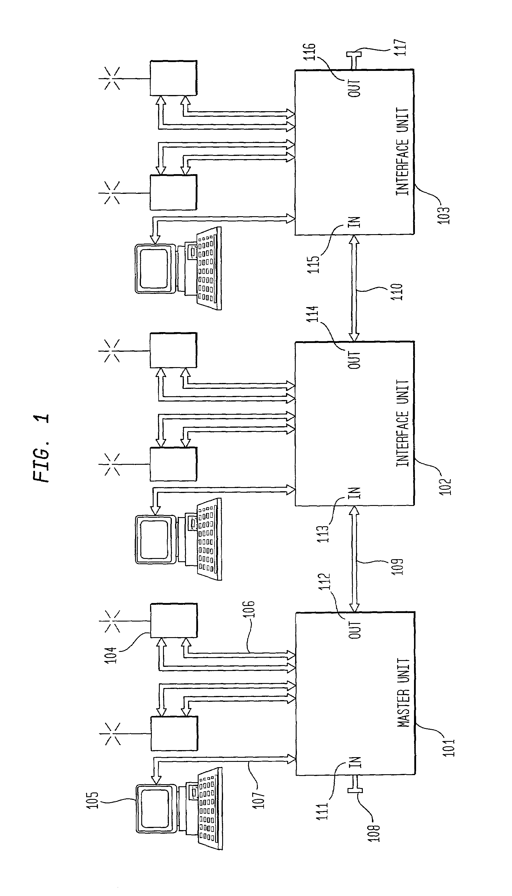
[0043]FIG. 1 is a block diagram illustrating the present invention in one embodiment. As shown, a master unit 101 is connected to interface units 102, 103. Additional interface units may be connected to the system. The connection between units is made using two pairs of twisted-pair conductors as found in category-5 or equivalent networking cable. The master unit and interface units each have an in-port 111, 113, 115 and an out-port 112, 114, 116 such that digital information is transmitted from the out-port of the master unit 112 to the in-port of interface unit 113 using one pair of twisted-pair cable 109. The interface unit processes the digital information and transmits it through its out-port 114 to the interface unit 103 using one pair of twisted-pair cable 110. Interface unit 103 processes the information and transmits it to its out-port 116. However, since no other interface unit is connected to the out-port of the interface unit 103, a seri...


PUM


Abstract

A method and system for communication within an energy-transmission-limited environment. RF transceivers throughout the site are located site-wide such that areas within the site in which communications are desired are within range of at least one of the RF transceivers. At each location RF transceivers are connected to a control unit. The control unit provides power to the transceivers and allows bi-directional communication of audio / voice and / or digital information. The control units may be networked to each other using standard network type category-5 or equivalent cables and may communicate to one another via the network connection. The control units may also be networked via an alternating current powerline by using an alternating current modem. The transceiver of the present invention utilizes single sideband modulators to modulate voice and / or digital signals. The signals are demodulated and filtered at a receiving end of the transceiver. A comb filter attenuates noisy signals with drifting harmonics.

Description

CROSS-REFERENCE TO RELATED APPLICATIONS[0001]This is a division of application Ser. No. 09 / 578,757, filed May 25, 2000. Application Ser. No. 09 / 578,757 claims the benefit of U.S. Provisional Patent Application Ser. No. 60 / 135,765 entitled METHOD AND APPARATUS FOR A MTNE COMMUNICATIONS SYSTEM, filed on May 25, 1999.DESCRIPTION TECHNICAL FIELD OF THE INVENTION[0002]The present invention relates generally to communication system and method, and more specifically, to a system and method for providing communications where the media limit electromagnetic energy transfers.BACKGROUND OF THE INVENTION[0003]Traditionally, in environments such as underground mines, industrial structures, and commercial complexes where electromagnetic energy transfer is blocked or limited by the media or obstacles, communication has been achieved by hardwired systems such as telephone lines. The demand for higher workers' safety and for higher productivity stimulated product developments in an effort to use wir...

Claims


Application Information

Patent Timeline
IPC IPC(8): H04B1/38H04L12/56H04W4/10H04W84/08
CPCH04B1/38H04W76/005H04W4/10H04B2203/5445H04W76/45Y02D30/70
Inventor MEIKSIN, ZVI H.PETRUS, T. BRADKILGORE, ROBERT J.
Owner TRANSTEK
Why Eureka
Eureka Blog
Learn More