Method of determining the elastoplastic behavior of components consisting of anisotropic material and use of the method

a technology of anisotropic materials and elastoplastic behavior, which is applied in the direction of instruments, force/torque/work measurement, apparatus, etc., can solve the problems of component fatigue and additional damage to be expected

Inactive Publication Date: 2006-05-23
GENERAL ELECTRIC TECH GMBH
View PDF5 Cites 4 Cited by
  • Summary
  • Abstract
  • Description
  • Claims
  • Application Information

AI Technical Summary

Benefits of technology

[0027]According to the principles of the present invention, the method is preferably used for determining the service life of gas turbine components under cyclic loading.

Problems solved by technology

The loading of the components is composed of forces, high thermal loads, oxidation and corrosion.
The mechanical and thermal loading leads in many cases to fatigue of the components after just a few thousand load cycles.
However, since inelastic calculations, which are often necessary, are as a rule not possible for reasons of cost and time, the service life prediction is based almost exclusively on linear-elastic stresses.
If the decisive loading at high temperatures acts for several minutes, additional damage can be expected.

Method used


Image

  • Method of determining the elastoplastic behavior of components consisting of anisotropic material and use of the method
  • Method of determining the elastoplastic behavior of components consisting of anisotropic material and use of the method
  • Method of determining the elastoplastic behavior of components consisting of anisotropic material and use of the method

Examples


Embodiment Construction

[0028]The material model on which the invention is based is derived from a plastic potential:

[0029]Ω=α⁢⁢σ02ER⁢n⁢(σv,ep2σ02)n(1)

where[0030]ER is the ‘reference’ stiffness. ER is incorporated in order to obtain the formal similarity of the compilation of formulas to that of the known isotropic case. ER is expediently selected in the order of magnitude of the elastic constant of the material considered, e.g. ER=100000 Nmm−2,[0031]Ω is the plastic potential of the material, from which the plastic strains are calculated by derivation with respect to the stresses,[0032]σ0 is a ‘reference’ stress which is expediently selected in the order of magnitude of the yield point, and[0033]σv,ep is an anisotropic equivalent stress (see below).

[0034]The plastic strains are then

[0035]ɛ_p⁢⁢l=∂Ω∂σ_ep(2)

[0036]From the plastic potential Ω, the plastic strains εpl are thus formed by partial derivation with respect to the stresses σep.

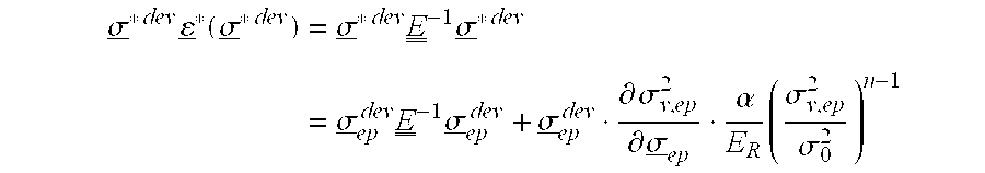
[0037]With equations (1) and (2)

[0038]∂Ω∂σ_ep=∂σv,ep2∂σ_ep⁢αER⁢(σv,ep2σ02...


PUM

PropertyMeasurementUnit
elastoplastic behavioraaaaaaaaaa
temperaturesaaaaaaaaaa
linear-elasticaaaaaaaaaa

Abstract

A method of determining the elastoplastic behavior of components, in particular of gas turbine plants, at high temperatures. First of all, the linear-elastic behavior is determined and the inelastic behavior is taken into account on the basis of the linear-elastic results by using the Neuber rule, the anisotropic characteristics of the components, as occur in particular through the use of single-crystalline materials, are taken into account in a simple manner by using a modified anistropic Neuber rule in the formσ*2=σep2⁡(1+A⁢C⁢αER⁢(A⁢⁢σep2σ02)n-1)whereA=inelastic anisotropic correction term,A=⁢12[F⁡(Dyy-Dzz)2+G⁡(Dzz-Dxx)2+⁢H⁢(Dxx-Dyy)2+2⁢L⁢⁢Dyz2+2⁢⁢MDz⁢⁢x2+2⁢⁢NDx⁢⁢y2] where F, G, H, L, M and N are the Hill constants,C=elastic anisotropic correction term, C=D•E−1•Dσ*=determined linear stress,σep=estimated inelastic stress,D=direction vector of the elastic and inelastic stressesE−1=inverse stiffness matrix,ER=reference stiffness,σ0=reference stress, and σα, n=material constants.

Description

[0001]This application is a Continuation of, and claims priority under 35 U.S.C. § 120 to, International application number PCT / CH03 / 00135, filed 21 Feb. 2003, and claims priority under 35 U.S.C. § 119 to Swiss application number 2002 0402 / 02, filed 8 Mar. 2003, the entireties of which are incorporated by reference herein.BACKGROUND OF THE INVENTION[0002]1. Field of the Invention[0003]The present invention relates to the field of analyzing and predicting the behavior of mechanical components.[0004]2. Brief Description of the Related Art[0005]The components in gas turbines (moving blades, guide blades, liners, etc.) are as a rule so highly stressed that they have only a finite service life. It is necessary to predict this service life for a reliable and economical design of gas turbines.[0006]The loading of the components is composed of forces, high thermal loads, oxidation and corrosion. The mechanical and thermal loading leads in many cases to fatigue of the components after just a...

Claims


Application Information

Patent Timeline
Patent Type & Authority Patents(United States)
IPC IPC(8): G01L1/00G01L3/00G01L5/00G06F19/00G01M99/00G01N3/00G01N3/02G01N3/32
CPCG01N3/02G01N3/60G01N2203/0007G01N2203/0246G01N2203/0094G01N2203/0218G01N2203/0226G01N2203/0075
Inventor BERNHARDI, OTTOMUECKE, ROLAND
Owner GENERAL ELECTRIC TECH GMBH
Why Eureka
Try Eureka