Film wrapping apparatus with negator spring biasing members

a film wrapping and negator spring technology, applied in the field of plastic film wrapping apparatus or system, can solve the problems of presenting maneuverability and control problems for operator personnel, affecting the operation of the apparatus, and being relatively large and not readily transportable,

Inactive Publication Date: 2006-05-30
ILLINOIS TOOL WORKS INC
View PDF23 Cites 14 Cited by
  • Summary
  • Abstract
  • Description
  • Claims
  • Application Information

AI Technical Summary

Benefits of technology

[0009]Another object of the present invention is to provide a new and improved portable plastic film wrapping apparatus or system for applying wrapping or packaging film to palletized loads or products wherein the various operational drawbacks and disadvantages, characteristic of PRIOR ART apparatus, systems, or methods of operating the same, are effectively overcome.
[0010]An additional object of the present invention is to provide a new and improved portable plastic film wrapping apparatus or system for applying wrapping or packaging film to palletized loads or products wherein as a result of the vertical movements of the film roll carriage of the film wrapping apparatus or system, along the vertical mast member, no longer being controlled by means of a counterweight mechanism but, to the contrary, being controlled by means of a negator spring assembly, the vertical mast member no longer needs to house or accommodate a counterweight mechanism whereby the height dimension of the vertical mast member can be substantially reduced.
[0011]A further object of the present invention is to provide a new and improved portable plastic film wrapping apparatus or system for applying wrapping or packaging film to palletized loads or products wherein as a result of the vertical movements of the film roll carriage of the film wrapping apparatus or system, along the vertical mast member, no longer being controlled by means of a counterweight mechanism but, to the contrary, being controlled by means of a negator spring assembly, the vertical mast member no longer needs to house or accommodate a counterweight mechanism whereby the height dimension of the vertical mast member can be substantially reduced such that destabilizing moment arms or forces are effectively eliminated so as to permit operator personnel to easily control the film wrapping apparatus or system during the film wrapping or packaging operation, and wherein, further, the width dimension of the apparatus or system can likewise be substantially reduced in view of the fact that the destabilizing moment arms or forces have been eliminated.
[0012]A last object of the present invention is to provide a new and improved portable plastic film wrapping apparatus or system for applying wrapping or packaging film to palletized loads or products wherein as a result of the vertical movements of the film roll carriage of the film wrapping apparatus or system, along the vertical mast member, no longer being controlled by means of a counterweight mechanism but, to the contrary, being controlled by means of a negator spring assembly, the vertical movements of the film roll carriage are not subjected to accelerated movements which would otherwise result in variable speeds of descent, and in addition, vertically movements of the film roll carriage may be achieved in an infinitely controlled manner.SUMMARY OF THE INVENTION
[0014]Accordingly, if continuous spiral wrapping of the palletized load or product is desired to be achieved while the operator walks, and simultaneously steers the apparatus or system, around the palletized load disposed at the wrapping station, the operator simply needs to actuate the control cable so as to effectively cause the pawl mechanism to be released from its engaged position with respect to the lift cable whereby the recoiling of the pair of negator springs will serve to elevate the film roll carriage at a constant rate of speed such that uniform wrapping of the palletized load or product within the packaging or wrapping film is able to be achieved. Alternatively, if continuous concentric wrapping of the palletized load or product within the packaging or wrapping film at a particular elevational level is desired, which is known as reinforcing wrapping, the control cable is not actuated whereby the pawl mechanism is maintained engaged with the lift cable such that further elevation of the film roll carriage, and the roll of wrapping film mounted thereon, is effectively prevented. At the completion of a wrapping cycle or operation, the operator can use either one of two alternative means for moving the film roll carriage in a downward mode from its elevated position, back toward its lowered START position, which effectively disengages the pawl mechanism from the lift cable and simultaneously causes the pair of negator springs to again be uncoiled in preparation for a subsequent palletized load or product film packaging or wrapping operation or cycle. The apparatus or system of the present invention also permits several operative components thereof to effectively be reversed whereby in lieu of the film roll carriage being elevated during a film-wrapping operation or cycle wherein the palletized load or product is normally wrapped in a direction proceeding upwardly from the bottom of the load or product, the film roll carriage can descend during a film-wrapping operation or cycle wherein the palletized load or product is wrapped in a direction proceeding downwardly from the top of the load or product.

Problems solved by technology

However, while it has been noted within the aforenoted U.S. Pat. No. 6,237,307 which issued to Zentmyer et al. that the disclosed apparatus or system is portable in that the same is mounted upon a platform which has wheels, rollers, or the like so as to render the same movable or mobile, the apparatus is nevertheless relatively large and not readily transportable so as to, in turn, not be readily or easily movable within a particular wrapping plant or facility, or even yet further, readily or easily transportable between different wrapping plants or facilities located at different production sites.
Such a clutch drive mechanism, however, is relatively complex and costly to incorporate within a portable film wrapping apparatus or system.
This vertical height or dimension of the vertical mast member may sometimes present maneuverability and control problems for the operator personnel, in connection with the performance of the wrapping operations as determined by means of the repetitive steering of the portable wrapping apparatus or system around the palletized load, particularly when the counterweight mechanism is disposed within the vicinity of the upper end portion of the vertical mast member.
The reason for this is that as a result of the remote disposition or location of the counterweight with respect to the base or platform of the apparatus or system, substantial moment forces or moment arms, as considered in connection with the center of gravity of the apparatus or system, are often adversely impressed upon the apparatus or system.

Method used


Image

  • Film wrapping apparatus with negator spring biasing members
  • Film wrapping apparatus with negator spring biasing members
  • Film wrapping apparatus with negator spring biasing members

Examples


Embodiment Construction

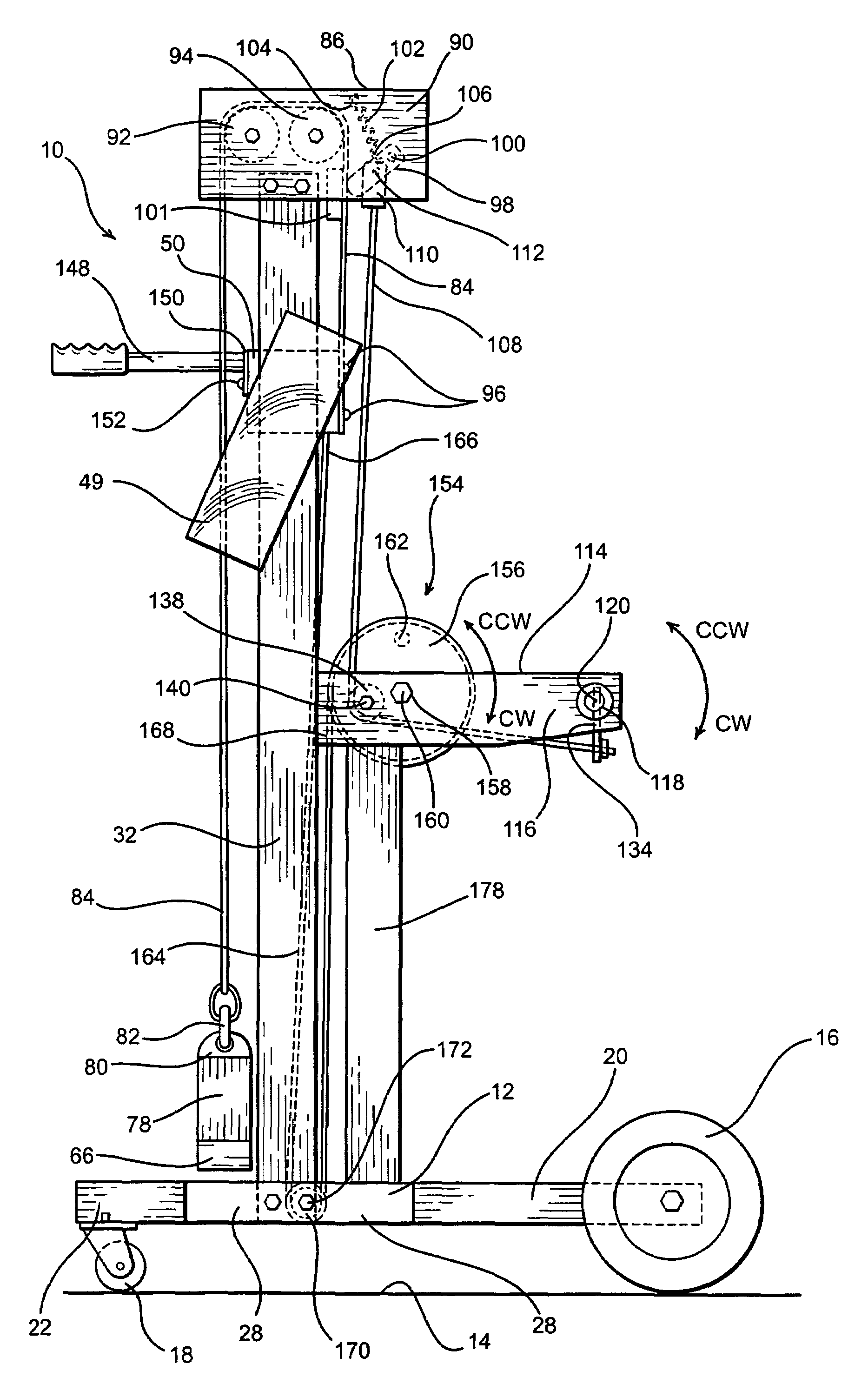
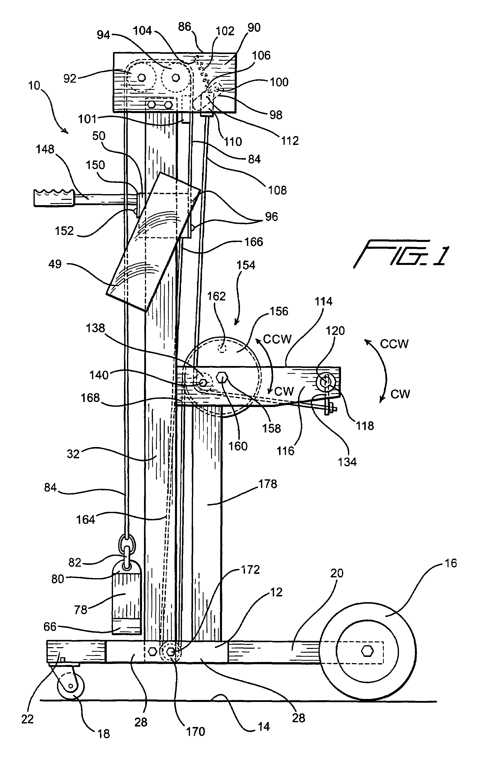
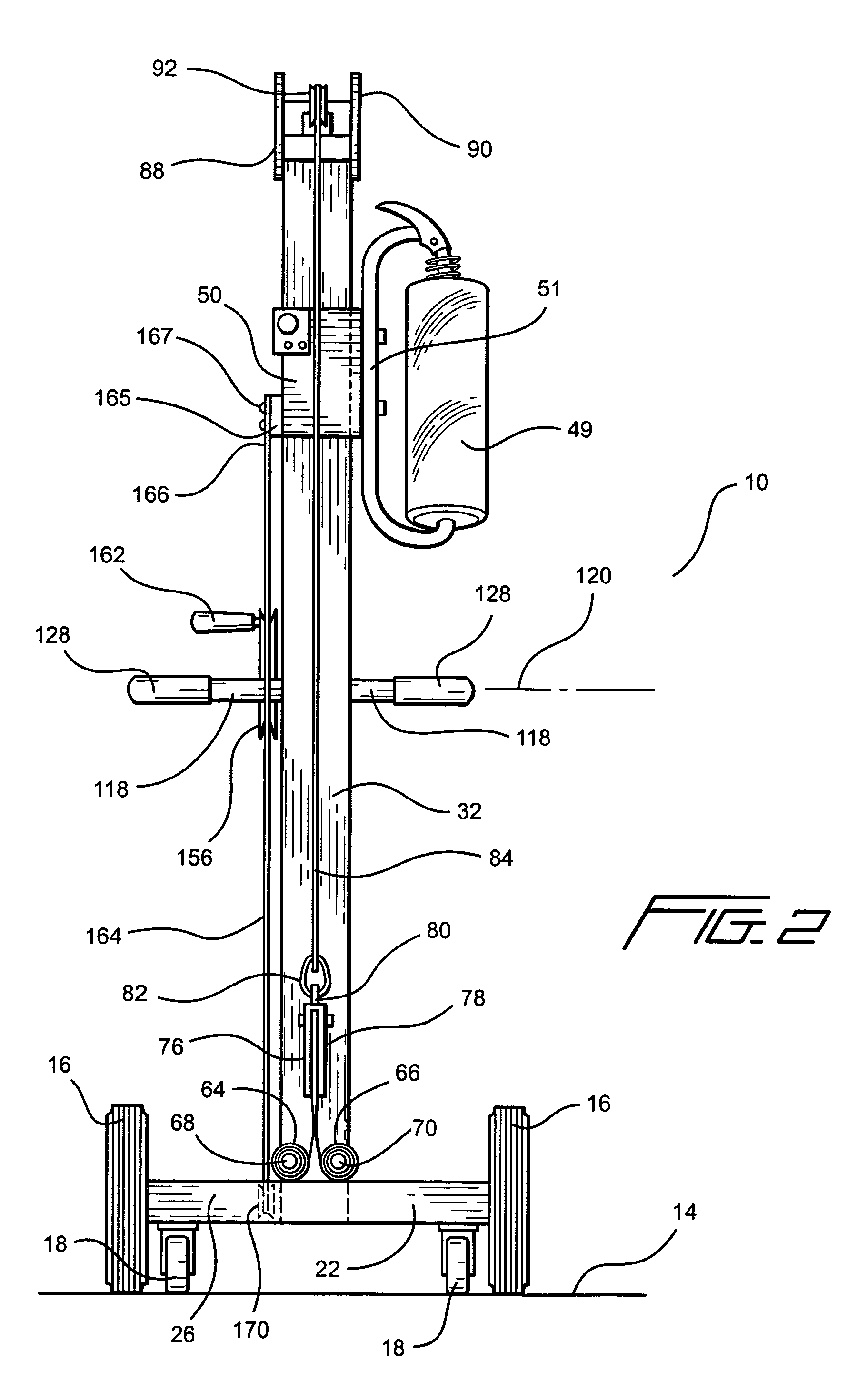
[0025]Referring now to the drawings, and more particularly to FIGS. 1,2,6, and 7 thereof, a first embodiment of a new and improved palletized load plastic film wrapping apparatus or system, constructed in accordance with the teachings and principles of the present invention, is disclosed and is generally indicated by the reference character 10. The apparatus or system 10 is mounted upon a movable cart which renders the entire apparatus or system 10 portable and transportable, and it is seen that the movable cart comprises a chassis or framework 12 which is adapted to be rollably supported and moved along a floor or ground region 14 by means of a pair of laterally or transversely spaced, non-pivotal rear wheels 16,16, and a pair of laterally or transversely spaced, pivotal or steerable front caster wheel assemblies 18, 18. In this manner, the entire palletized load plastic film wrapping apparatus or system 10 can be easily moved and steered around a suitable workstation at which the ...


PUM

PropertyMeasurementUnit
height dimensionaaaaaaaaaa
heightaaaaaaaaaa
vertical heightaaaaaaaaaa

Abstract

A portable plastic film wrapping system comprises a push-cart having a vertical mast member mounted thereon, and a film roll carriage is vertically movable along the mast member. The film roll carriage is operatively connected to negator spring members by a film roll carriage lift cable, and a holding pawl mechanism is adapted to be movable between ENGAGED and DISENGAGED positions with respect to the film roll carriage lift cable. When the holding pawl mechanism is moved to its DISENGAGED position, the negator spring members cause the film roll carriage to be vertically elevated, whereas when the holding pawl mechanism is disposed at its ENGAGED position, movement of the film roll carriage lift cable, and the film roll carriage, is effectively prevented. The film roll carriage can also be controllably moved in both upward and downward directions so as to achieve bottom-to-top, as well as top-to-bottom, wrapping modes of operation upon palletized loads.

Description

FIELD OF THE INVENTION[0001]The present invention relates generally to a plastic film wrapping apparatus or system for wrapping palletized loads or products within plastic wrapping film, and more particularly to a new and improved plastic film wrapping apparatus or system wherein the new and improved plastic film wrapping apparatus or system has incorporated therein a negator spring assembly, as opposed to a conventional counterweight mechanism, for controlling the elevational movements of the film roll carriage assembly of the film wrapping apparatus or system, whereby as a result of effectively eliminating the counterweight mechanism, characteristic of conventional, prior art plastic film wrapping apparatus or systems, and replacing the same with the aforenoted negator spring assembly, the vertical extent or overall height dimension of the vertical mast member, along which the film roll carriage assembly is movable when a film wrapping operation is being performed, may be substant...

Claims


Application Information

Patent Timeline
Patent Type & Authority Patents(United States)
IPC IPC(8): B65B13/04B65B11/02B65B67/08
CPCB65B67/085B65B11/025
Inventor HUSON, GALE W.
Owner ILLINOIS TOOL WORKS INC
Why Eureka
Try Eureka