Endotracheal tube pressure monitoring system and method of controlling same

a pressure monitoring system and endotracheal tube technology, applied in mechanical equipment, valves, operating means/releasing devices, etc., can solve the problems of insufficient ventilation of patients, inability to control the flow of air to patients, and inability to monitor the pressure of patients. to achieve the effect of high probability of blockag

Inactive Publication Date: 2006-05-30
UNIV OF FLORIDA
View PDF14 Cites 81 Cited by
  • Summary
  • Abstract
  • Description
  • Claims
  • Application Information

AI Technical Summary

Benefits of technology

[0014]In one embodiment, the pressure lines may include a first pressure line that is in fluid communication with the distal end of the endotracheal tube so that a tracheal pressure may be measured. Because of the high probability of blockage due to its proximity to the trachea and lungs of the patient, this first pressure line may also be in fluid communication with the purging subsystem so that the patency of the first pressure line may be maintained. Alternatively, in another embodiment, the pressure lines may include a second pressure line that is in fluid communication with the proximal end of the endotracheal tube. This second pressure line enables the measurement of airway pressure. The second pressure line may also be in fluid communication with the purging subsystem.
[0015]In an alternative embodiment, the pressure monitoring system may have a pressur

Problems solved by technology

Obstructions within the pressure lines may result in erroneous tracheal and/or airway pressure readings.
Without the correct pressure measurements of tracheal pressure and/or airway pressure, the derived data based on the incorrect pressure measurements are predisposed to be in error, which may result in insufficient ventilation of the patient.
Additional

Method used


Image

  • Endotracheal tube pressure monitoring system and method of controlling same
  • Endotracheal tube pressure monitoring system and method of controlling same
  • Endotracheal tube pressure monitoring system and method of controlling same

Examples


first embodiment

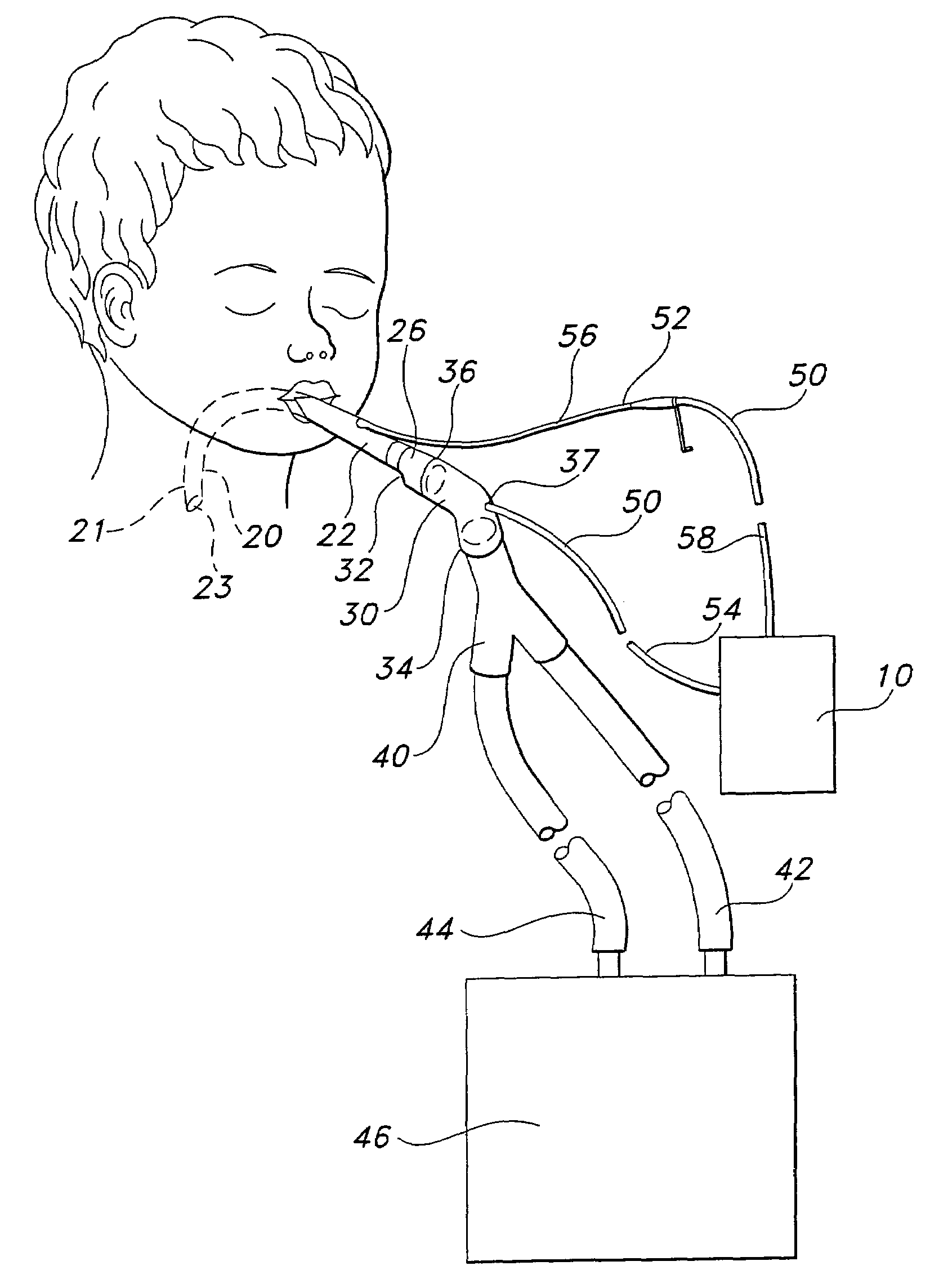
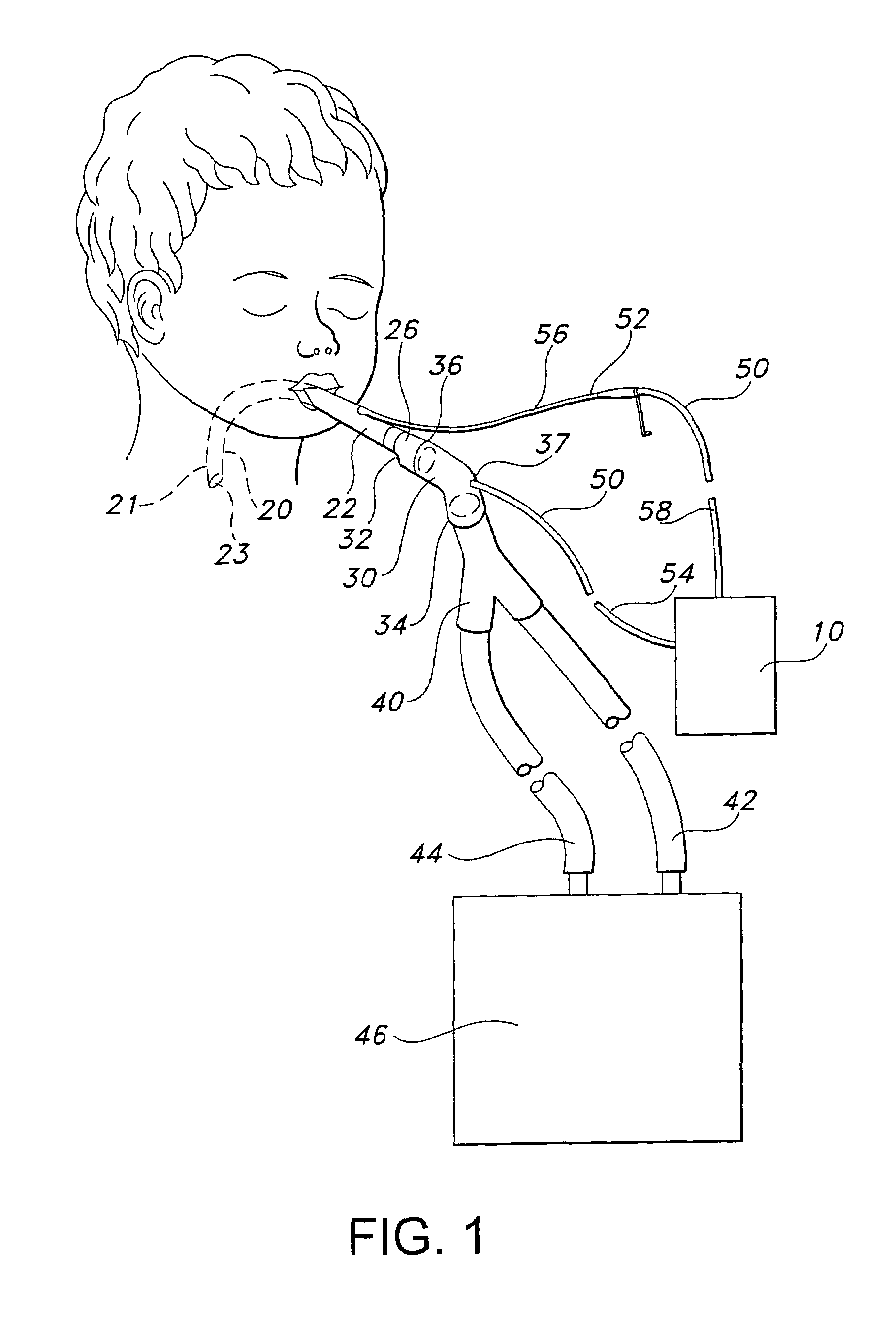
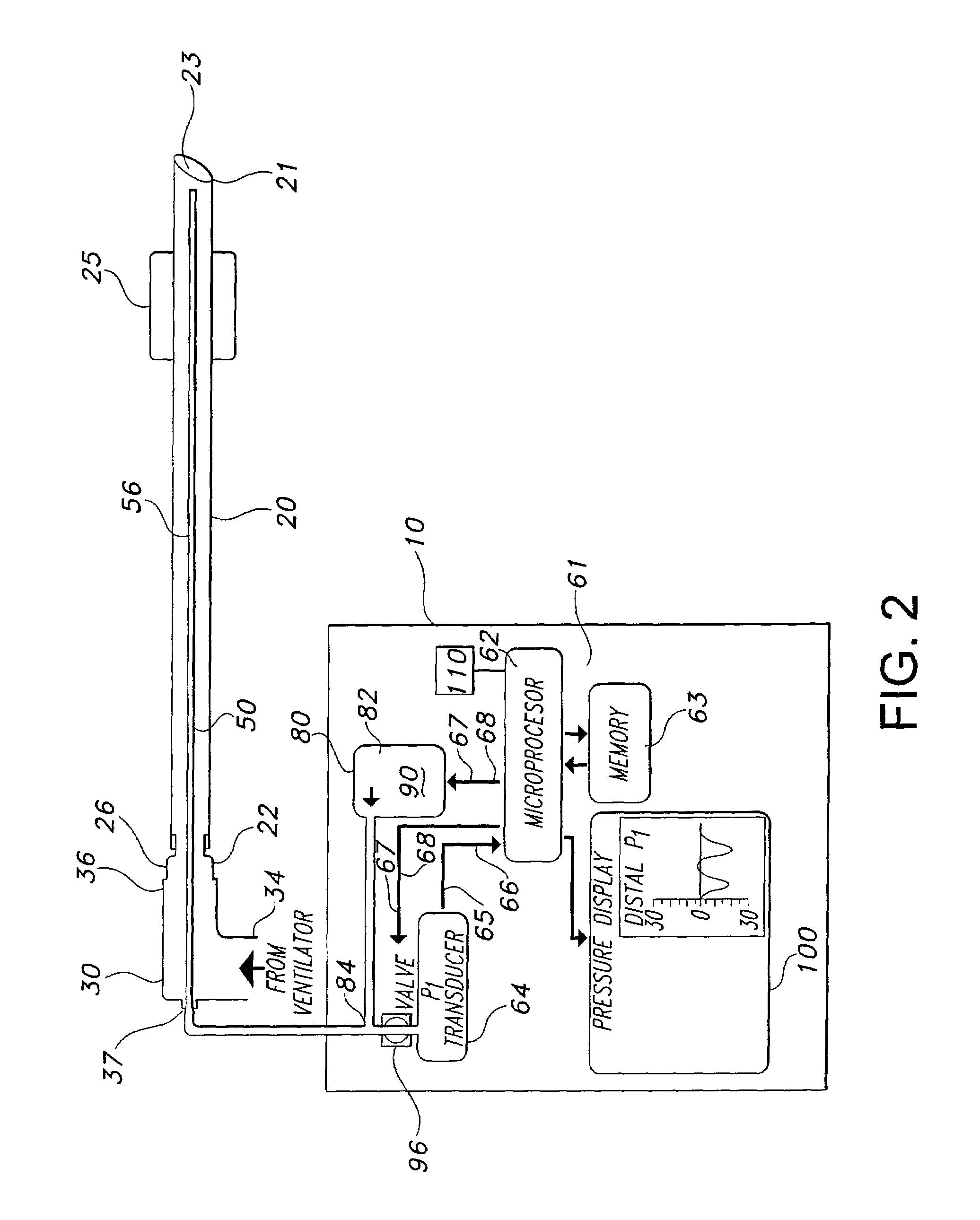
[0055]Referring now to FIG. 2, an exemplified endotracheal tube pressure monitoring system 10 is shown. Here, the endotracheal tube 20 is connected to the connector 30 which is, in turn, connected to the ventilator. The endotracheal tube 20 is inserted into the trachea of the patient so that the distal end 21 of the endotracheal tube 20 is placed in fluid communication with the trachea of the patient.

[0056]The endotracheal tube pressure monitoring system 10 is shown with one pressure line 50. This pressure line 50 is in fluid communication with the distal end 21 of the endotracheal tube 20. Because of the likelihood that the pressure line 50 used in this embodiment will become obstructed due to water or mucus plugs (due to pressure line's 50 proximity to the body fluids in and around the trachea), this example of the system is shown with the pressure line 50 in fluid communication with the purging subsystem 80. The purging subsystem 80 is shown with the source of pressurized fluid 8...

second embodiment

[0058]Referring now to FIG. 3, an exemplified endotracheal tube pressure monitoring system 10 is shown. In this embodiment, the system has a first pressure tube in fluid communication with the distal end 21 of the endotracheal tube 20 and a second pressure tube connected to a port of the connector 30 and in fluid communication with the proximal end 22 of the endotracheal tube 20. Airway pressure may be determined by the fluid within the first pressure line 52 communicating with a first pressure transducer 64 operably attached to the first pressure line 52. Similarly, tracheal pressure may be determined by the fluid within the second pressure line 54 which, is in communication with a second pressure transducer 64 operably attached to the second pressure line 54.

[0059]The purging subsystem 80, which includes here, for example, one fluid pump 90, and the first purging actuator 96, is in fluid communication with the first pressure line 52 so that the first pressure line 52 may be mainta...

fourth embodiment

[0061]Referring to FIG. 5, the endotracheal tube pressure monitoring system 10 is shown. In this embodiment, the system has a first pressure tube in fluid communication with the distal end 21 of the endotracheal tube 20 and a second pressure tube connected to a port of the connector 30 and in fluid communication with the proximal end 22 of the endotracheal tube 20. The airway pressure may be determined by the fluid within the first pressure line 52 communicating with a first pressure transducer 64 operably attached to the first pressure line 52. Similarly, tracheal pressure may be determined by the fluid within the second pressure line 54, which is in communication with a second pressure transducer 64 operably attached to the second pressure line 54.

[0062]Here, for example, the purging subsystem 80 includes two fluid pumps 90 and two purging actuators 96. The first fluid pump 90 in fluid communication with the first pressure line 52 and the second fluid pump 90 in fluid communicatio...


PUM


Abstract

An endotracheal tube pressure monitoring system for an endotracheal tube having at least pressure sensor in communication with a major lumen of the endotracheal tube, and a pressure monitoring subsystem in operative communication with the pressure sensor. The system may also have at least one fluid pressure line in fluid communication with the major lumen and in operative communication with the pressure monitoring subsystem to monitor the pressure of fluid within each respective fluid pressure line, and a purging subsystem in fluid communication with the fluid pressure line. Each fluid pressure line that is in fluid communication with the purging subsystem being selectively purged by the purging subsystem when pressure monitoring subsystem determines the respective pressure line has become obstructed. Purging the fluid pressure line maintains the patency of the pressure line so that accurate pressure measurements within the endotracheal tube can be obtained for calculation of parameters in lung mechanics. It is emphasized that this abstract is provided to comply with the rules requiring an abstract which will allow a searcher or other reader to quickly ascertain the subject matter of the technical disclosure. It is submitted with the understanding that it will not be used to interpret or limit the scope or meaning of the claims. 37 C.F.R. §1.72(b).

Description

[0001]This application is a continuation-in-part of U.S. patent application, Ser. No. 10 / 245,444, filed Sep. 16, 2002, now abandoned which is a continuation of, and claims priority to, U.S. patent application, Ser. No. 09 / 641,986, filed Aug. 17, 2000, which issued as U.S. Pat. No. 6,450,164 on Sep. 17, 2002, which is fully incorporated herein.BACKGROUND OF THE INVENTION[0002]1. Field of the Invention[0003]The present invention relates to a system and methods used to determine pressure measurements within an endotracheal tube for use in calculation of parameters in lung mechanics and for use in determining the patency of the endotracheal tube. More specifically, the present invention is related to a system having at least one pressure sensor in communication with a major lumen of the endotracheal tube to ensure the viability of pressure measurements for subsequent use in calculation of parameters in lung mechanics and for use in determining the patency of the endotracheal tube, parti...

Claims


Application Information

Patent Timeline
IPC IPC(8): A61M16/00A61M11/00A61M15/00A61M16/04
CPCA61M16/04A61M2205/50A61M2016/0021A61M16/042A61M16/0833A61M16/0858A61M2016/0027
Inventor BANNER, MICHAEL J.BLANCH, PAUL B.EULIANO, NEIL R.
Owner UNIV OF FLORIDA
Why Eureka
Try Eureka