Synthetic resin bottle with circumferential ribs for increased surface rigidity

a synthetic resin and bottle body technology, applied in rigid containers, packaging, large containers, etc., can solve the problems of reducing the degree of negative pressure absorption, affecting the causing a marked damage to the outer appearance of the bottle, so as to achieve the effect of increasing the level of surface rigidity

Inactive Publication Date: 2006-05-30
YOSHINO KOGYOSHO CO LTD
View PDF21 Cites 61 Cited by
  • Summary
  • Abstract
  • Description
  • Claims
  • Application Information

AI Technical Summary

Benefits of technology

[0018]In the configuration of claim 2 where the bottle has a cylindrical shape, the body wall outwardly forms a convex surface, which gives high surface rigidity to the entire body.
[0023]The body can be equipped with a number of circumferential ribs, including those disposed at the upper end and the lower end of the body, so that the body wall has an increased level of surface rigidity.

Problems solved by technology

However, since the body, a major part of the bottle, has a thin wall, the bottle is inconvenient in that a part of the body may falsely become dented and deform under a reduced pressure created inside the bottle and may give a marked damage to the outer appearance of the bottle.
As a commercial product, the bottle may be quite poor in appearance.
However, the deformable panel walls in the above-described conventional art has a problem in that the extent to which negative pressure can be absorbed is not sufficient, considering the extent of dented deformation created under the reduced pressure.
Another problem of the deformable panel walls is that the body has a decreased buckling strength due to the existence of these deformable panels, which are molded by denting and deforming a part of the walls and which are equally spaced in a row around the circumference of the body.
Still another problem of the deformable panels is that the bottle sometimes looks poor in appearance.
Lastly, there is a problem that the bottle becomes permanently deformed.
Since these deformable panel walls have a shape of simply curved and dented panels, the panels cannot fully absorb the pressure.

Method used


Image

  • Synthetic resin bottle with circumferential ribs for increased surface rigidity
  • Synthetic resin bottle with circumferential ribs for increased surface rigidity
  • Synthetic resin bottle with circumferential ribs for increased surface rigidity

Examples


first embodiment

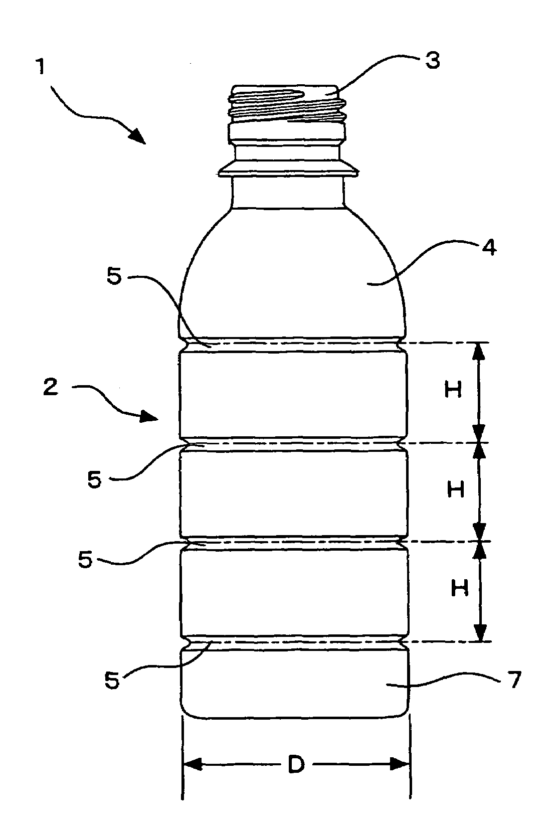
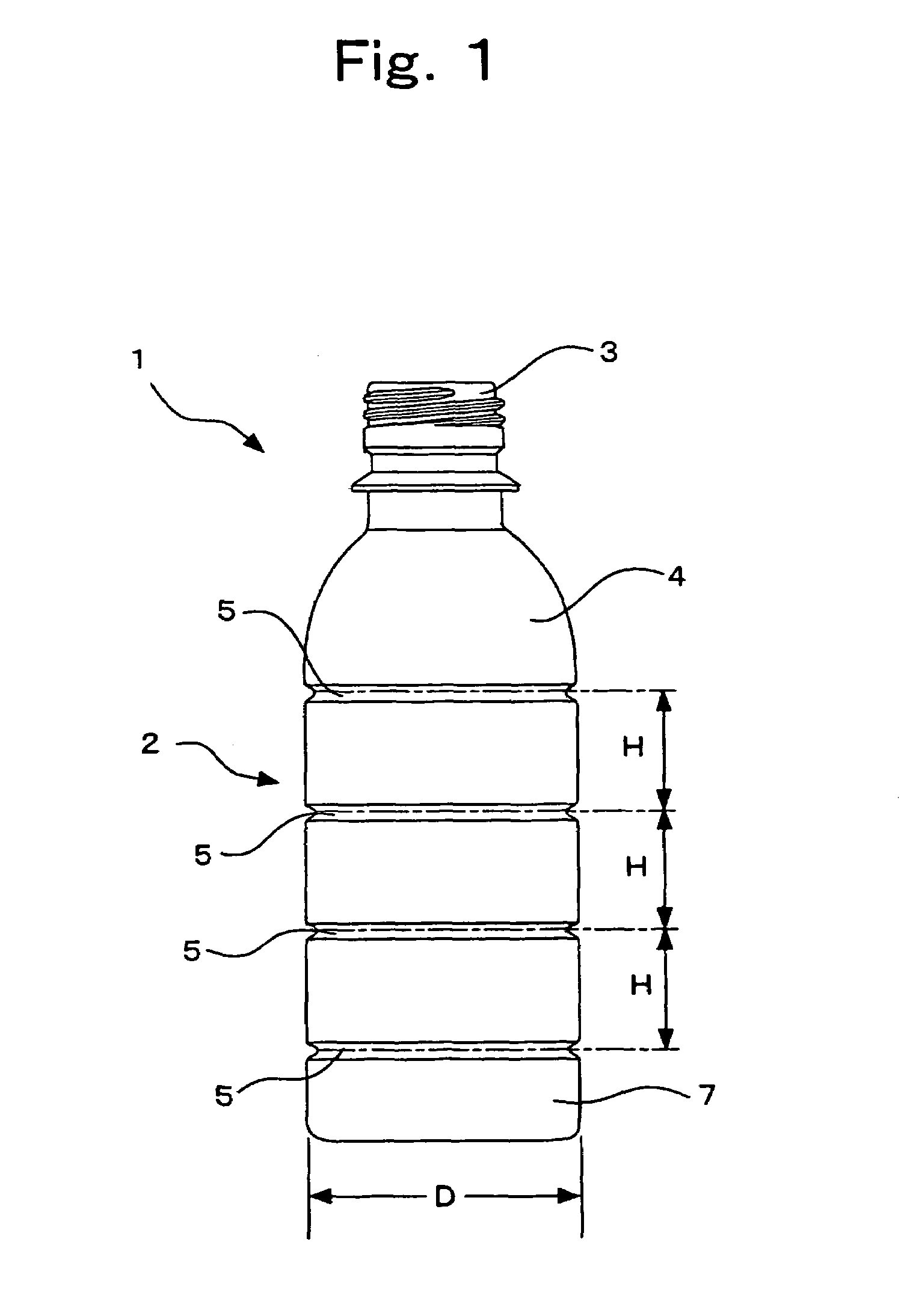
[0034]This invention is further described with respect to preferred embodiments, now referring to the drawings. FIG. 1 is a front view of an entire synthetic resin bottle in this invention. It is an ordinary 200-ml PET bottle, which has been biaxially drawn and blow-molded. In its structure, the bottle comprises cylindrical body 2, shoulder 4 of a truncated conical shape disposed at the upper end of the body 2, short cylindrical neck 3 disposed on the shoulder 4, and bottom 7 at the lower end of the body 2. The bottle 1 has the cylindrical body 2 with a diameter of 54 mm, and has a total bottle height of 140 mm. The body 2 has an average thickness of 350 μm and a minimum thickness of at least 300 μm.

[0035]The body 2 is provided with a total of four circumferential ribs 5 having a cross-section of almost U-shape. Among these ribs, the uppermost rib is disposed at the upper end of the body 2 near the border with the shoulder 4. The lowermost rib is disposed at the lower end of the bod...

second embodiment

[0044]The bottle 1 of the filled with the contents, and the retort-packed bottle was heat-treated at 121° C. for 30 minutes. The bottle 1 was then cooled down to room temperature and was checked for any deformation. No dented deformation was observed. This bottle 1 had a depressurizing strength of 525 mmHg (70.0 kPa). Even for the pressure reduction derived from the treatment at such a high temperature, sufficient surface rigidity can be secured within the range of wall thickness that is permissible for the bottle, by setting a suitable distance H between two adjacent circumferential ribs 5.

[0045]The shape of this bottle obviously allows the bottle to be applicable also as an ordinary hot-filling bottle that has been biaxially drawn, blow-molded and can be heat-treated at a temperature in the range of 85 to 95° C. This shape of the bottle is not limited merely to the use as the retort-treated bottle.

third embodiment

[0046]FIG. 4 shows a synthetic resin bottle in this invention. The bottle has an average wall thickness of 350 μm, the cylindrical body 2 with the cross-section of a regular dodecagonal shape, a diagonal length of 54 mm, and five circumferential ribs 5 that are spaced equally. There was no dented deformation that was caused by the hot filling at a temperature of 87° C.

[0047]The circumferential ribs 5 are spaced equally in all of the first, second, and third embodiments. However, it is noted that these ribs need not necessarily be spaced equally. If they are not spaced equally, the purpose of this patent application can be achieved at the widest distance H in the range of 0.2D to 0.6D, and more preferably in the range of 0.3D to 0.45D, between two adjacent circumferential ribs 5.

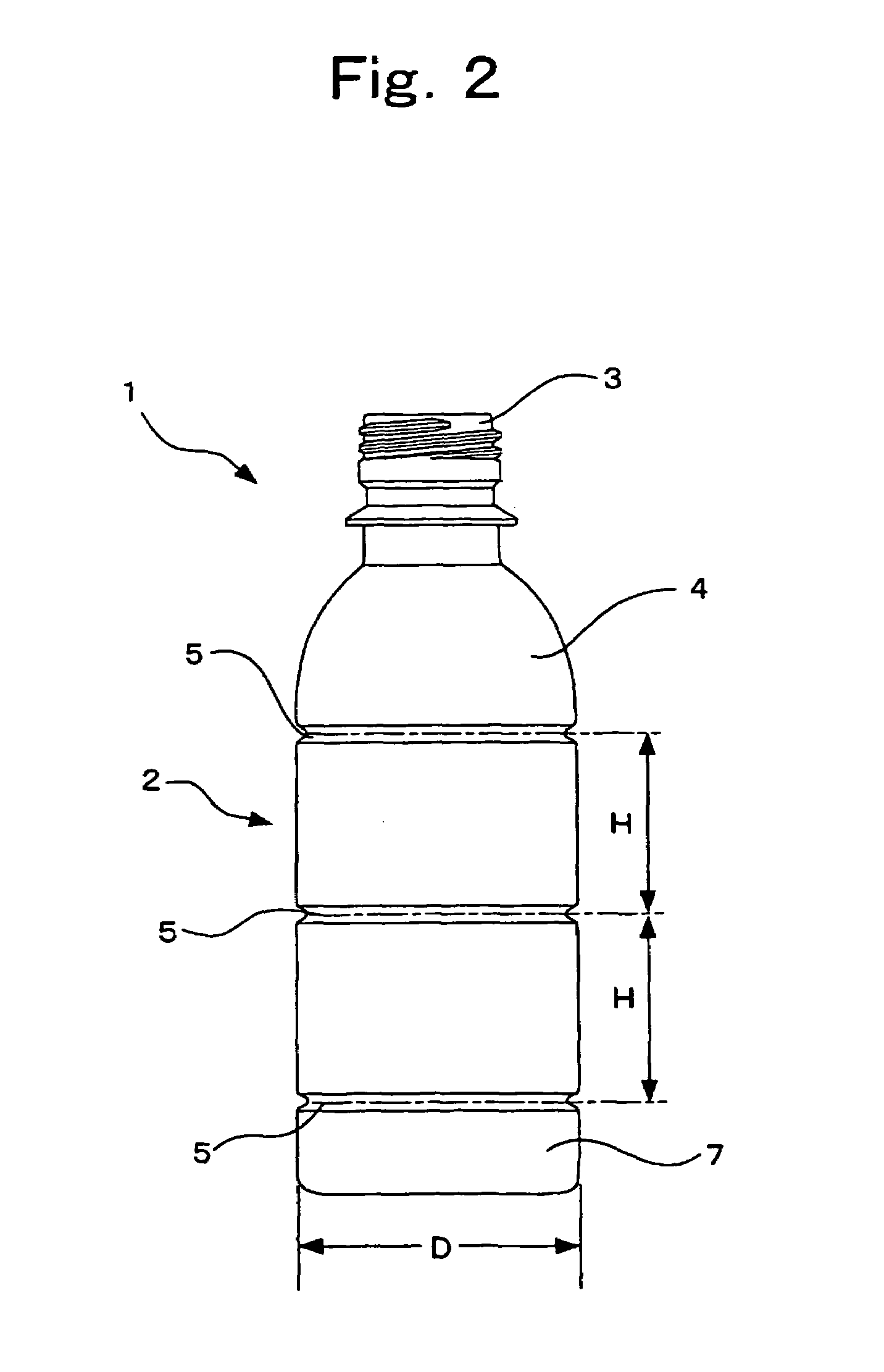
[0048]FIG. 5 shows a synthetic resin bottle in the fourth embodiment of this invention. Two circumferential ribs 5 are disposed at the upper end and the lower end, respectively, of the body 2. Between these t...


PUM


Abstract

The technical problem of this invention is to eliminate the need to use deformable panel walls and to find the body of a shape that no false deformation, such as dented deformation, takes place in a portion of the body due to the hot filling of the contents or the reduced pressure created by the treatment of retort-packed foods. The object of this invention is to obtain a bottle that can inhibit the deformation caused by reduced pressure, has a high buckling strength, and is good in outer appearance. As the solution, there is provided a biaxially drawn, blow-molded bottle made of a synthetic resin, in which the surface rigidity of the wall of body is set in such a manner that a part of the body wall cannot become dented inward under a reduced inner pressure of at least 350 mmHg (46.7 kPa).

Description

TECHNICAL FIELD[0001]This invention relates to a biaxially drawn, blow-molded bottle made of a synthetic resin, especially made of a polyethylene terephthalate resin for use in hot filling of the contents.BACKGROUND OF THE INVENTION[0002]The biaxially drawn, blow-molded bottle of a polyethylene terephthalate resin (hereinafter referred to as the PET resin) can be given a thin and uniform wall thickness because of distinguished characteristics of PET. Since such bottles are economical, have high resistance to contents and a high mechanical strength, and have good outer appearance, the bottles are widely used as liquid containers in various fields.[0003]As described above, the PET bottle has a high mechanical strength despite its thin wall. However, since the body, a major part of the bottle, has a thin wall, the bottle is inconvenient in that a part of the body may falsely become dented and deform under a reduced pressure created inside the bottle and may give a marked damage to the ...

Claims


Application Information

Patent Timeline
Patent Type & Authority Patents(United States)
IPC IPC(8): B65D1/02B65D1/46B65D1/44
CPCB65D1/0223B65D1/44B65D2501/0036B65D1/02
Inventor ONODA, YUKOOZAWA, TOMOYUKIIIZUKA, TAKAOTOMIYAMA, SHIGERUNAKAYAMA, TADAYORITANAKA, FUMINORIASARI, TSUTOMU
Owner YOSHINO KOGYOSHO CO LTD
Why Eureka
Try Eureka