Labeling device for bound materials

a technology of bound materials and labels, applied in the direction of identification means, scarves, instruments, etc., can solve the problems of difficult labeling of the spine of such materials, complicated installation, and difficulty in labeling the edge of such binders, and achieve the effect of easy attachment and removal

Inactive Publication Date: 2006-05-30
PARK ANDY
View PDF19 Cites 11 Cited by
  • Summary
  • Abstract
  • Description
  • Claims
  • Application Information

AI Technical Summary

Benefits of technology

[0015]It is therefore an advantage of the present invention to provide a labeling device suitable for labeling variously sized binders.
[0016]Another advantage of the present invention is to provide a labeling device that can easily be attached to, and removed from the spine or edge of a binder.

Problems solved by technology

Materials bound by the methods described above are generally thinner than materials bound using traditional book binding methods, making the spine of such materials difficult to label.
Further, because coil-type binders do not contain a spine, it is particularly difficult to label the edge of such binders.
Prior devices developed to label the spine of comb-type binders had to be sized to fit the exact width of the binder, or required complicated installation.

Method used


Image

  • Labeling device for bound materials
  • Labeling device for bound materials
  • Labeling device for bound materials

Examples


Embodiment Construction

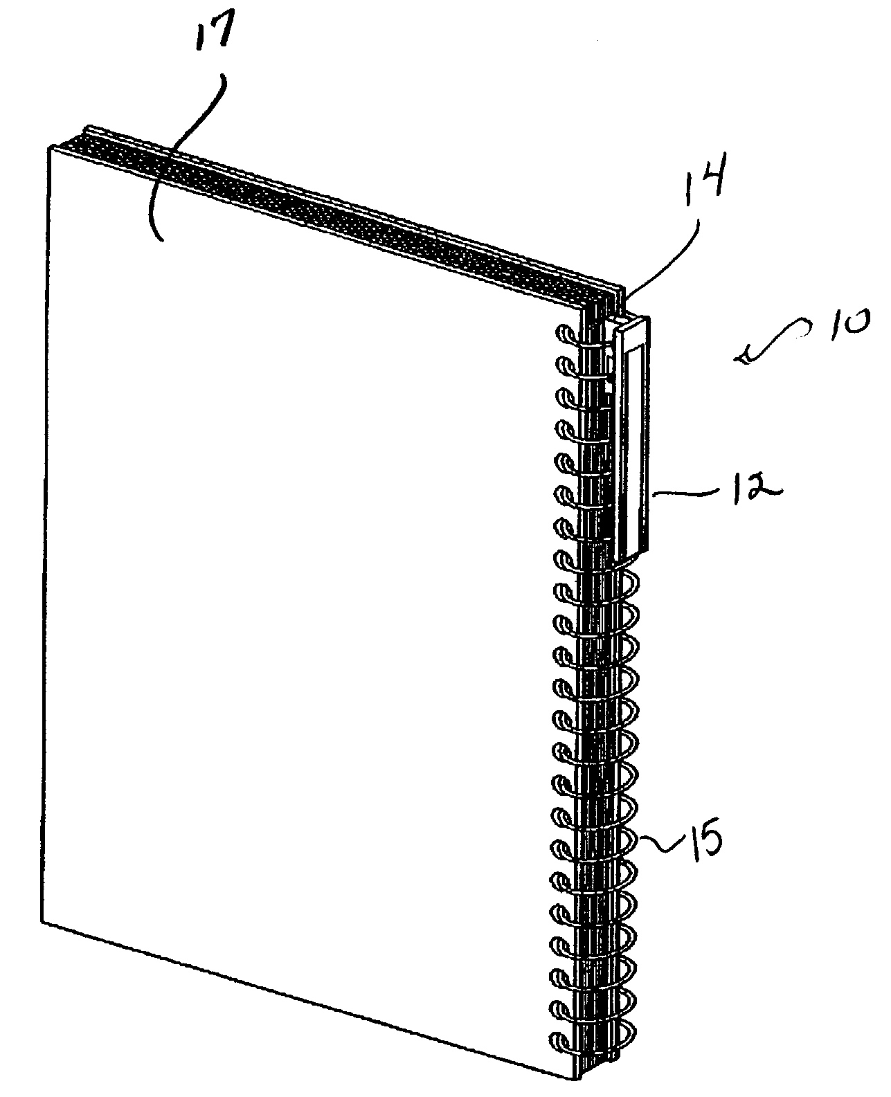
[0023]The present invention relates to an apparatus for labeling the spine or edge of a binder. The labeling device of the present invention provides a detachable labeling system for use with various types of binders. The term “binder” as used herein refers to any device used for securing paper or other materials such as coil binders, comb-type binders, loop wire binders, twin loop binders and the like.

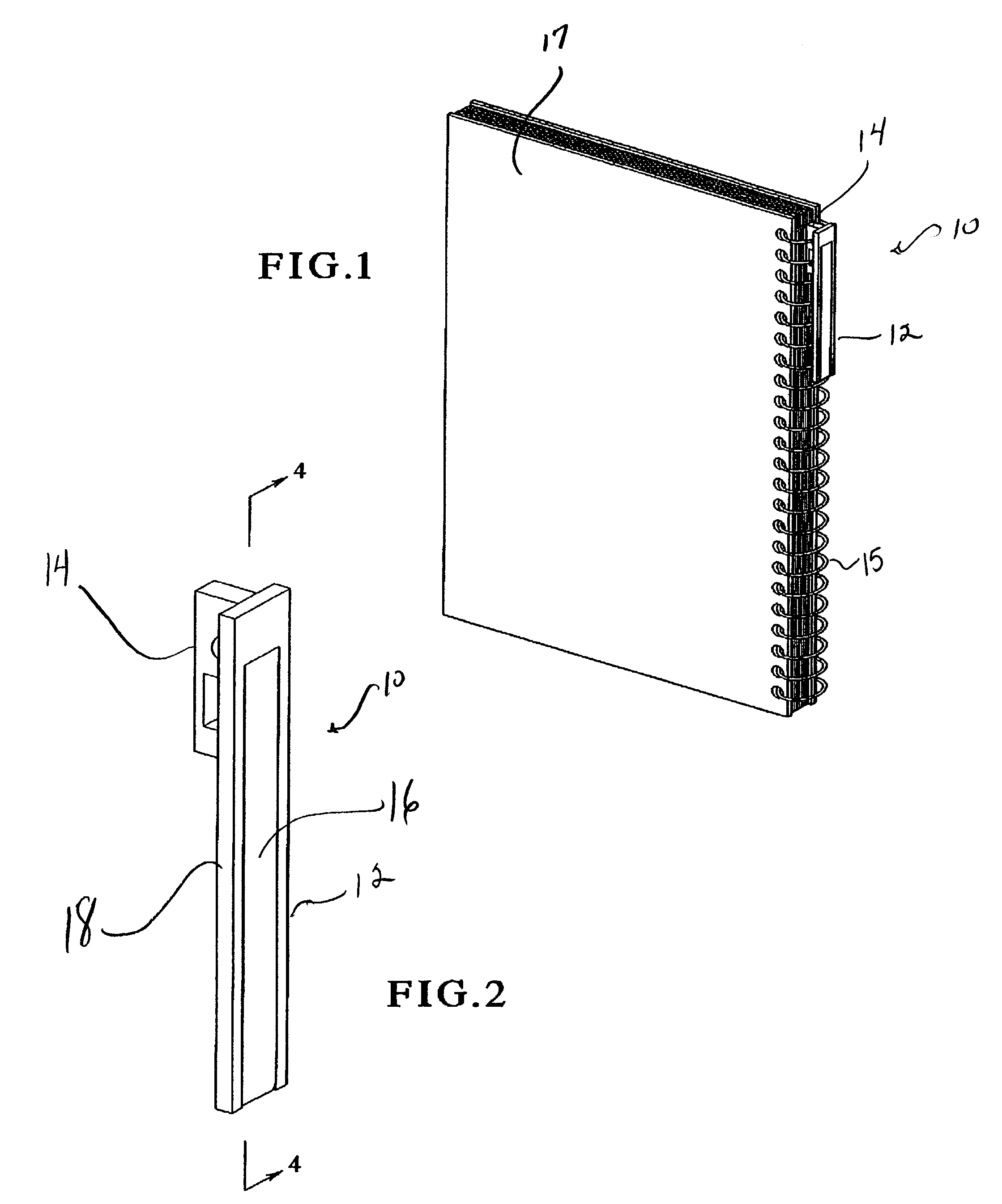
[0024]One embodiment of the labeling device according to the present invention is shown in FIGS. 1 to 5 and is generally indicated by numeral 10. The labeling device 10 includes a housing 12 for encasing a label 28 and a clip 14 for attaching the labeling device 10 to the spine or edge 15 of a binder 17.

[0025]FIG. 1 illustrates an example of the labeling device 10 of the present invention attached to a set of materials bound with a spiral or coil-type binder 17. The housing 12 of the labeling device 10 encloses a label 28 and is attached to the edge of the binder 17 by means of a clip...


PUM


Abstract

The present invention relates to an apparatus for labeling the spine or edge of a binder. In an embodiment, the device comprises a housing, a clip attached to the housing and a label encased within the housing. The housing further comprises a base portion and a cover portion, wherein the cover portion is adapted to enclose a label within the base portion of the labeling device.

Description

PRIORITY CLAIM[0001]This application is a non-provisional application of, claims priority to, and the benefit of U.S. Provisional Application Ser. No. 60 / 368,876 filed on Mar. 29, 2002, the entire contents of which are incorporated herein.BACKGROUND OF THE INVENTION[0002]The present invention generally relates to labeling devices, and more particularly relates to labeling devices used to label the spine or edge of a binder.[0003]Comb-type and coil-type binding elements are commonly used to bind materials together for low-volume binding applications. Comb-type binders include a spine having a plurality of curled, spaced fingers integral with the edge of the spine at one end, and free at the other end. The free end of the fingers are fed through apertures in the materials to be bound and curl to rest resiliently against the opposite edge of the spine.[0004]Coil-type or spiral binders are composed of a continuous coil which is fed through a series of spaced holes along the edge of a st...

Claims


Application Information

Patent Timeline
Patent Type & Authority Patents(United States)
IPC IPC(8): B42D3/00B42D1/06
CPCB42D1/06Y10T24/20Y10S402/50Y10T24/44017Y10T24/1335Y10T24/205Y10T24/1382Y10T24/44855Y10T24/264Y10T24/202Y10T24/1394Y10T24/44863Y10T24/44769Y10T24/201B42P2221/04
Inventor PARK, ANDY
Owner PARK ANDY
Why Eureka
Try Eureka